This article proposes hypothetical solutions for constructing modular piling in Arctic nearshore conditions considering the distribution of loads during operation in seasonally flooded areas. The research is taken from Litvinenko, V. S et al's paper published in the International Journal of Mining Science and Technology.
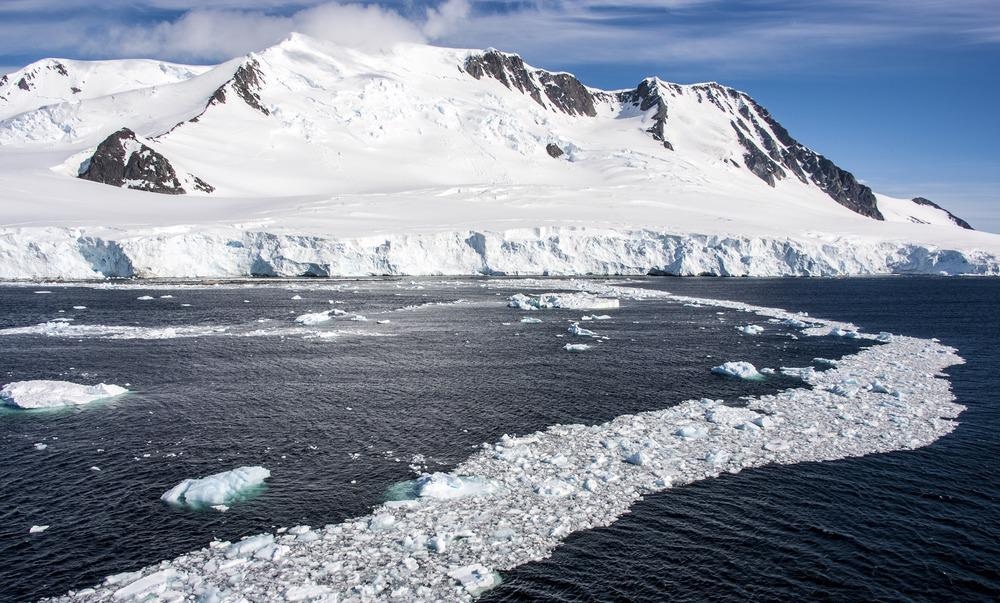
Image Credit: Ion Mes/Shutterstock.com
Oil and gas field development requires the construction of facilities called islands. The earlier constructs or islands were enclosed with sandbags, gravel caisson, and a caisson on a water-filled berm. They were thought to be a safe and effective temporary drilling base for marine exploration.
During 1970–1980, construction of ice islands occurred, and more than 40 ice island facilities were built. The temporary nature of the island along with its minimized environmental impact makes approval for the construction process easier. It is necessary to examine the technology in areas subjected to flooding before installing ice piling foundations on the Arctic shelf.
The concept of developing modular piling foundations represented by pipes assumes the optimal placement and year-round operation of the drilling equipment and auxiliaries in the identified process areas.
Figure 1 depicts a modular piling foundation linked by roads, including facilities such as a drilling rig, boiler house, inhabited camp, power station, diesel-electric generator, and petrol, fuel, and lubricants (F/L) warehouse.
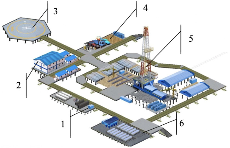
Figure 1. Placement of equipment on island sites of the modular piling foundation, where 1 – Island of fire-fighting equipment safety zone, R = 30 m, R is the radius in meters; 2 – Inhabited camp; 3 – Helicopter pad safety zone, R = 40 m; 4 – Island of machinery parking and maintenance of transport facility and equipment; 5 – Drilling rig safety zone, R = H + 10 m, where H is the drilling rig height; and 6 – F/L island-water house safety zone, R = 40 m. Image Credit: Litvinenko et al., 2021.
The equipment is kept on the foundation considering the safety zones for carrying out work. The dimensions of the drilling rig platform were determined to assure the optimal process of well drilling with delivery and supply of the necessary equipment.
Modeling Modular Piling Foundations
The type of foundation should be chosen considering the loads due to wind and sea-level changes. In the Arctic Shelf, ice conditions in the waters of the Ob and Taz Bays are one of the unfavorable ones (Figure 2), but they do harbor significant reserves of energy resources.
Figure 2. Ice conditions in the water areas of Ob and Taz Bays. Image Credit: Litvinenko et al., 2021.
It is also not possible to use conventional sand dumps due to the lack of roads and deposits of suitable construction sand. Modular pile foundations can be created and placed on the coastline of the Arctic waters in such conditions.
Designing modular piling foundations depends on the loads acting on the platforms from the facilities located on them. Figure 3 shows the maximum load from equipment and equipment operating on the basis.
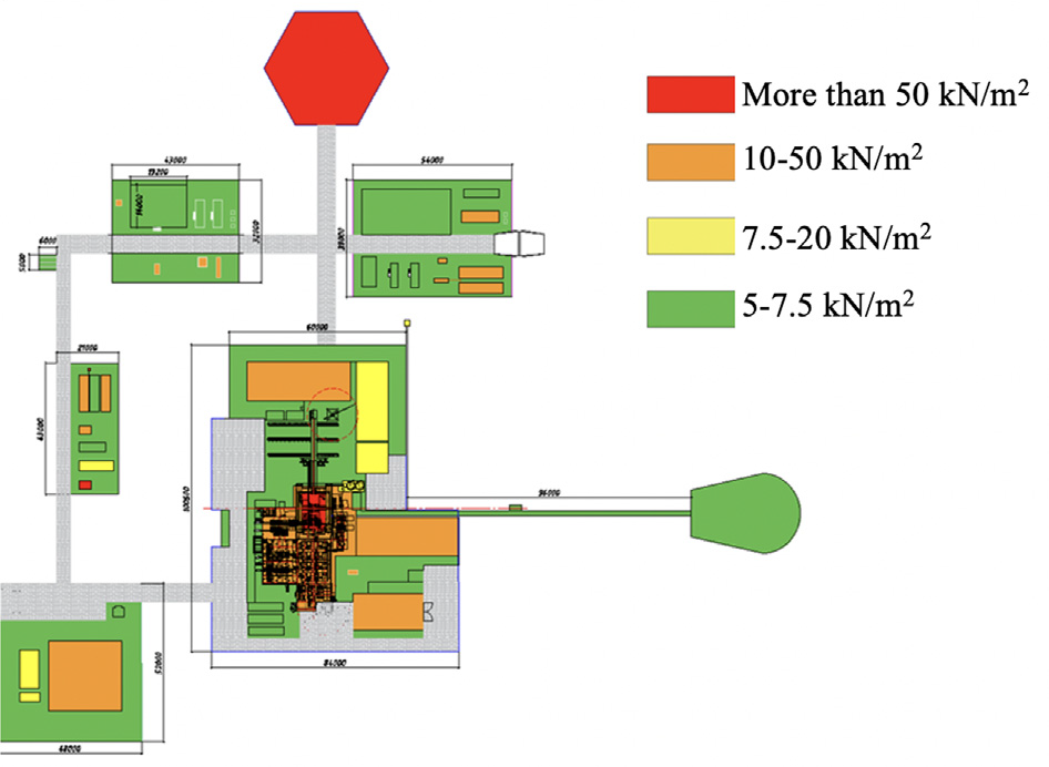
Figure 3. Identification of areas of normal and elevated process loads. Image Credit: Litvinenko et al., 2021.
Figure 4 shows the design of a bored pile with a bearing side surface and Figure 5 depicts the procedure for installing piles.
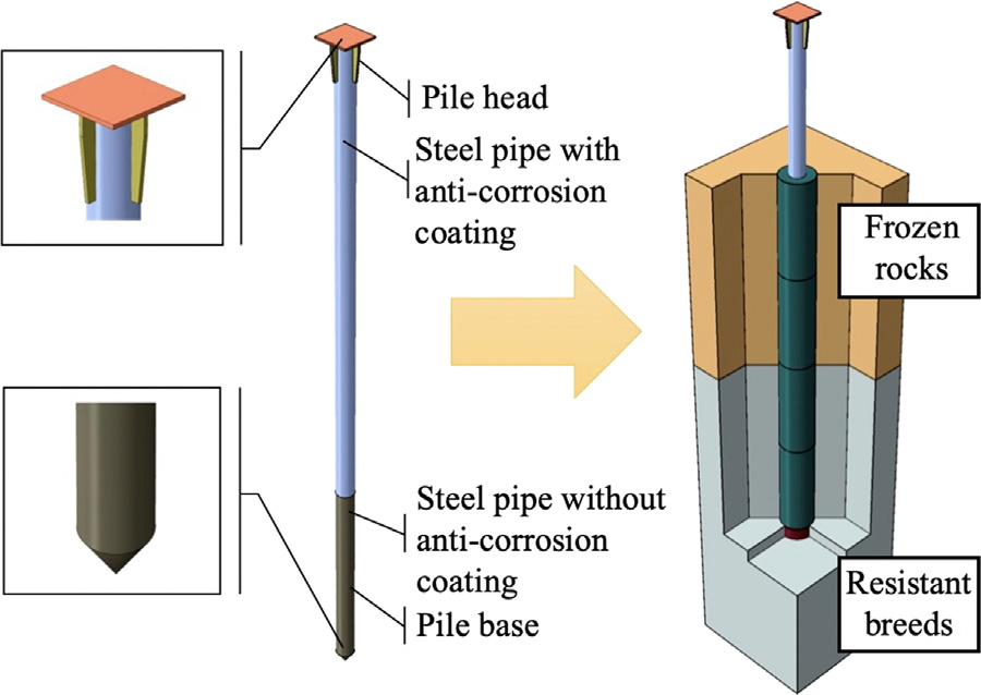
Figure 4. Construction of a bore pile with a bearing side surface. Image Credit: Litvinenko et al., 2021.
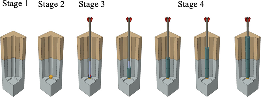
Figure 5. Process flow diagram of driven-in cast-in-situ piles, where Stage 1 – Well construction; Stage 2 – Installation of gravel cushion; Stage 3 – Pile installation; and Stage 4 – Multilayer filling of the space between the well walls and pile with thawed/frozen ground with packing. Image Credit: Litvinenko et al., 2021.
Table 1 details the thermophysical characteristics of the pile material and cement for the calculation.
Table 1. Thermophysical characteristics of the pile material. Source: Litvinenko, et al., 2021.
| Material |
Density
(kg/m3) |
Coefficient of thermal
conductivity (W∙m−1∙K−1) |
Heat capacity
(J∙kg−1∙K−1) |
| Steel |
7850 |
3,880,000 |
500 |
| Cement-sand mortar |
2200 |
12,960 |
850 |
| Pipe filling material |
2200 |
12,960 |
850 |
Changes in temperature conditions influence the bearing capacity of soils. Figure 6 depicts the annual data for various parameters in the Yamal Peninsula.
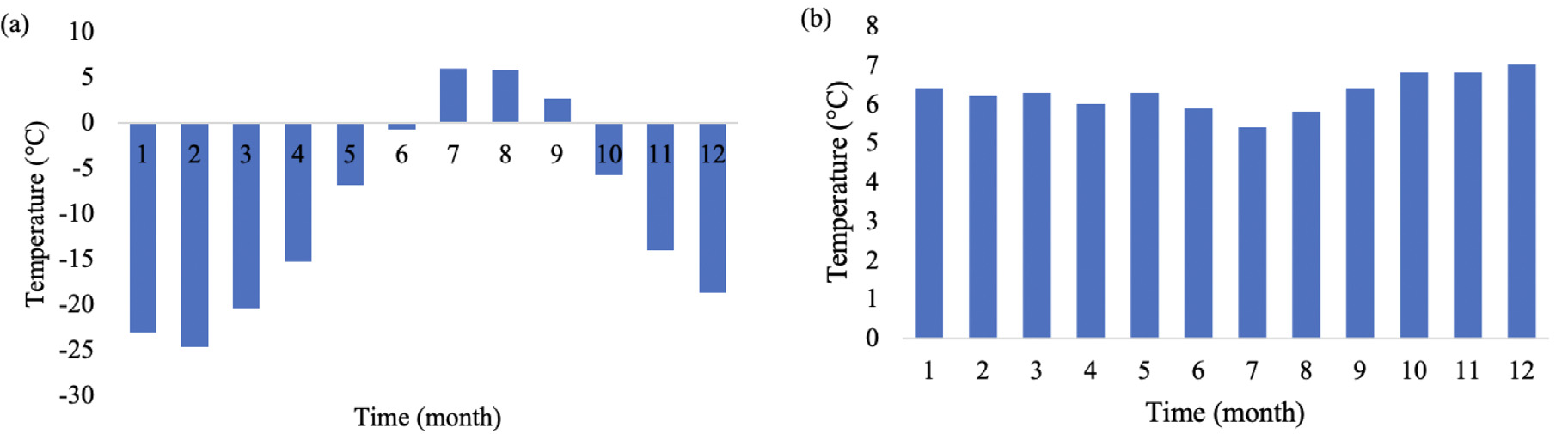
Figure 6. Data for average annual temperature (a), wind speed (b) by the year. Image Credit: Litvinenko et al., 2021.
Thermophysical characteristics of soils in thawed and frozen conditions are used as the soil parameters. Tables 2 and 3 details the input parameters for modeling the thermodynamic condition of frozen ground and its deformation.
Table 2. Parameters of the rheological behavior model of permafrost soils. Source: Litvinenko, et al., 2021.
| Type of frozen ground |
Model parameter |
| b |
n |
w |
σc0 (MPa) |
| Clay soils |
0.33 |
2.38 |
1.20 |
0.17 |
| 0.45 |
2.50 |
0.97 |
0.18 |
| Loamy soils |
0.15 |
2.04 |
0.87 |
2.25 |
| 0.37 |
3.70 |
0.89 |
0.31 |
| 1.00 |
3.00 |
0.60 |
0.07 |
Sandy and sandy-
loam soils |
0.45 |
1.28 |
1.00 |
1.05 |
| 0.63 |
2.63 |
1.00 |
0.16 |
| Icy soils |
0.40 |
2.00 |
1.00 |
0.30 |
| 1.00 |
3.00 |
0.37 |
0.10 |
Notes: εc = 10-5h-1; and εe=(σe/σcθ)n(εct/b)b.
Table 3. Thermophysical characteristics of permafrost soils. Source: Litvinenko, et al., 2021.
| Type of soil |
Thermophysical indicator of permafrost soils |
ρd.th
(kg/m3) |
Wtot, unit
fraction |
Cp
(J∙kg−1∙K−1) |
λth
(W∙m−1∙K−1) |
λf
(W∙m−1∙K−1) |
Cw
(J∙kg−1∙K−1) |
Ci |
L0
(J/kg) |
Cth.sp
(J∙kg−1∙K−1) |
Cf.sp
(J∙kg−1∙K−1) |
Tbf
(°C) |
| Sandy soils |
1.58 |
0.23 |
750 |
2.50 |
2.86 |
4.2 |
2.06 |
335 |
1.416 |
1.219 |
−0.19 |
| Sandy-loam soils |
1.63 |
0.25 |
850 |
1.80 |
1.96 |
|
|
|
1.803 |
1.472 |
−0.25 |
| Loamy soils |
1.61 |
0.30 |
950 |
1.51 |
1.68 |
|
|
|
1.904 |
1.520 |
−0.30 |
Notes: ρd.th is the density of thawed soil in dry condition in kg/m3; Wtot the total moisture; Cp the specific heat capacity of soil framework in J∙kg-1∙K-1; λth the thermal conductivity factor for soils in thawed state inW∙m-1∙K-1; Ci the specific heat capacity of ice in J∙kg-1∙K-1; L0 the heat of phase conversions water–ice in J/kg; Cth.sp the specific heat capacity of soil in thawed state in J∙kg-1∙K-1; Cf.sp the specific heat capacity of soil in frozen state in J∙kg-1∙K-1; and Tbf the temperature at the beginning of soil freezing in °C.
The examination results revealed that ambient air temperature is from +5 °C to −25 °C and that the average annual wind speed is from 5.5 to 7.0 m/second.
Figure 7 depicts the temperature of the frozen soils based on thermophysical calculations.
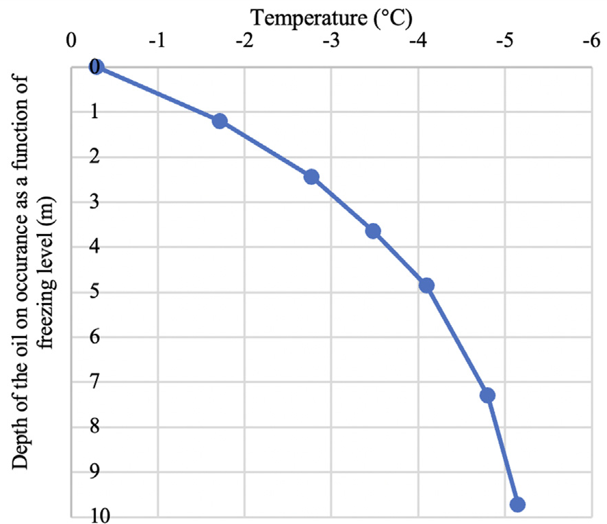
Figure 7. Temperature distribution typical for construction conditions in the zone of frozen soils. Image Credit: Litvinenko et al., 2021.
The major maximum stresses and the resultant deformations in the soil body are illustrated in Figures 8, 9, and 10.
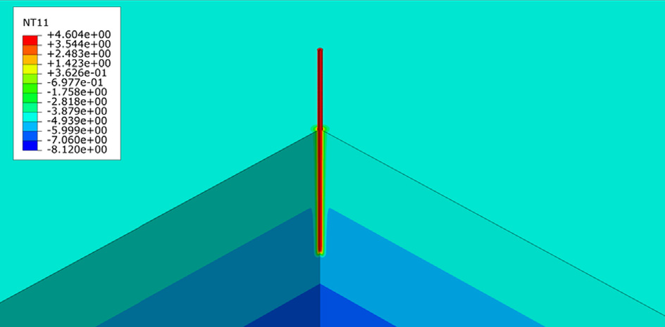
Figure 8. Temperature distribution (°C) at the stage of pile freezing into the soil body. Image Credit: Litvinenko et al., 2021.
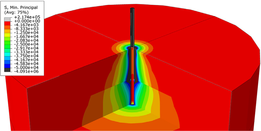
Figure 9. Main maximum stress distribution (Pa) in the soil body. Image Credit: Litvinenko et al., 2021.
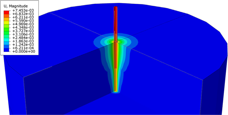
Figure 10. Resulting deformations distribution (m) in the pile and soil body. Image Credit: Litvinenko et al., 2021.
Results
Results of forecasting the bearing capacity of a single pile with different schemes to organize thermal stabilization of soils are listed in Table 4, while Table 5 details the stress state of load-bearing elements of an echelon-type drilling platform.
Table 4. Typical results of forecasting the bearing capacity of a single pile with various schemes for organizing thermal stabilization of soils. Source: Litvinenko, et al., 2021.
| Year |
Bearing capacity (t) |
| |
Horizontal cooling
units solution |
Vertical cooling units
solution 3.0 × 3.0 m |
Vertical cooling units
solution 1.5 × 1.5 m |
| 1 |
26.91 |
33.33 |
56.19 |
| 2 |
57.90 |
53.40 |
71.81 |
| 3 |
69.43 |
59.99 |
76.99 |
| 4 |
71.51 |
64.63 |
78.70 |
Table 5. Stress state of load-bearing elements of an echelon type drilling platform. And Figure 11 illustrates the distribution of equivalent stresses (Pa). Source: Litvinenko, et al., 2021.
Distance between
supports (m) |
Load on one
pile (t) |
Maximum stress in
pile/column (MPa) |
Maximum stress in
cross beam (MPa) |
| 3.0 |
39.6–46.9 |
89.8–106.0 |
109.4–128.6 |
| 1.5 |
35.3–45.2 |
79.8–102.1 |
105.2–124.0 |
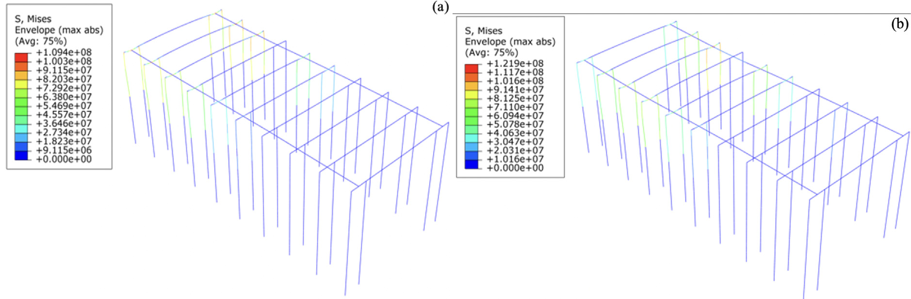
Figure 11. Distribution of equivalent stresses (Pa) in the load-bearing elements of an echelon-type drilling platform depending on the position of the drilling rig. Image Credit: Litvinenko et al., 2021.
Table 6 enlists the calculation of the cost of backfilling for a remote exploration well in the north of the Yamal Peninsula and Table 7 details the cost of the construction of pile sites for the same.
Table 6. Results of calculation. Source: Litvinenko, et al., 2021.
| Cost type |
Amount in prices of 1 sq. 2021,
thousand dollars |
| Mechanical and manual earthworks |
51,730 |
| Construction materials |
93,517 |
| Transportation of goods by road |
557,364 |
| Maintaining the dump in operational condition |
329,731 |
| Total |
1,030,989 |
Table 7. Results of calculation. Source: Litvinenko, et al., 2021.
| Cost type |
Amount according to preliminary
calculations, thousand dollars |
Drilling wells for piles and
construction and installation works |
54,054 |
Materials for construction work, incl.
piles and prefabricated steel structures |
94,595 |
| Transportation of goods by road |
81,081 |
| Total |
229,730 |
The results obtained depict that the temperature at the area of pile contact with rock ranges from 1.75 °C to 1.50 °C and that the maximum stresses in the soil body differ from 4 kPa to 5 kPa. The results gained meet the requirements of safe construction of modular piling foundations under Arctic conditions.
Technical Discussion
This article highlights the issue of gas-saturated precipitation is highlighted as fine-lying gas in the soil reduces its strength which might result in critical movements of platforms and numerous emergencies.
Conclusion
Modular pile foundations on the shallow Arctic shelf require comprehensive analysis due to various issues. The research results reveal the temperature at the area of pile contact with rock and the strength calculations revealed the necessity of one pile per 1 m2.
The study also evaluated the cost of development and maintenance of these islands. Remote year-round monitoring of changes in the modular piling foundation stressed-deformed condition is intended.
Journal Reference
Litvinenko, V. S., Dvoynikov, M. V., Trushko, V. L. (2021). Elaboration of a conceptual solution for the development of the Arctic shelf from seasonally flooded coastal areas. International Journal of Mining Science and Technology. Available at: https://doi.org/10.1016/j.ijmst.2021.09.010.
References and Further Reading
- Hewitt, K (2014) Arctic Offshore Islands - Lessons Learned. In: Proceedings of the OTC Arctic Technology Conference. Houston, Texas.
- Riley, J G (1976) The Construction Of Artificial Islands In The Beaufort Sea. Journal of Petroleum Technology. 28 (4), pp. 365–371. doi.org/10.4043/2167-MS.
- National standard of Russia (2012) 27217-2012: Soils. Method of Field Determination of Specific Tangential Forces of Frost Heave. Federal Agency of Technical Regulation and Metrology.
- Gadd, P. E., et al. (2021) The History of Artificial Islands for Oil Exploration and Development in the Alaskan Artic. In: Proceedings of the OTC Arctic Technology Conference. One Petro. doi.org/10.4043/23817-MS.
- Angell, V. W., et al. (1991) Case History: Ice Island Drilling Application and Well Considerations in Alaskan Beaufort Sea. Society of Petroleum Engineers, 6 (1), pp. 60–64 doi.org/10.2118/19947-PA.
- Bowles, H. T., et al. (1987) Drilling Considerations on Spray Ice Island Structures. A Case History, OCS-Y-0302 Well No. 1, Beaufort Sea, Alaska. In: Proceedings of the SPE Annual Technical Conference and Exhibition. OnePetro. doi.org/10.2118/16672-MS.
- Gao, L., et al. (2020) Research on the energy evolution characteristics and the failure intensity of rocks. International Journal of Mining Science and Technology, 30 (5), pp. 705–713. doi.org/10.1016/j.ijmst.2020.06.006.
- Feng, J., et al. (2020) Experimental and numerical study of failure behavior and mechanism of coal under dynamic compressive loads. International Journal of Mining Science and Technology, 30 (5), pp. 613–62. doi.org/10.1016/j.ijmst.2020.06.004.
- IPC E02B 17/00: Method for Constructing an Offshore Drilling Platform on the Shallow Shelf of Arctic Seas (2019) Russia: Patent No. 270445.
- Hannigan, P. J., et al. (2016) Geotechnical Engineering Circular. Berg & Associates, Woodbury, MN.
- Lyazgin A. L, et al. (2001) The analysis of methods of decrease frost heave forces for pile foundations under conditions of the North of Tyumen province. In: Proceedings of the 2nd Conference of Geocryologists of Russia. Moscow.
- Li, N & Xu, B (2008) A new type of pile used in frozen soil foundation. Cold Regions Science and Technology, 53 (3), pp. 355–368. doi.org/10.1016/j.coldregions.2007.10.005.
- Suleiman, M. T., et al. (2006) Cyclic Lateral Load Response of Bridge Column-Foundation-Soil Systems in Freezing Conditions. Journal of Structural Engineering, 132 (11), pp. 1745–1754. doi.org/10.1061/(ASCE)0733-9445(2006)132:11(1745).
- Yang, Z. J., et al. (2007) Seasonal frost effects on the soil-foundation-structure interaction system. Journal of Cold Regions Engineering, 21 (4), pp. 108–120.
- You, Y., et al. (2017) Causes of pile foundation failure in permafrost regions: The case study of a dry bridge of the Qinghai-Tibet Railway. Engineering Geology, 230, pp. 95–103. doi.org/10.1016/j.enggeo.2017.10.004.
- Dong, J., et al. (2012) Design ice load for piles subjected to ice impact. Cold Regions Science and Technology, 71, pp. 34–43. doi.org/10.1016/j.coldregions.2011.11.002.
- Construction Codes and Regulations. 2.02.04-88: Substructures and Foundations on Permafrost Soils. 2005 Moscow: State building of Russia.
- Russian Code of Practice. 25.13330.2012: Substructures and Foundations on Permafrost Soils. Updated Revision of SNiP 2.02.04-88 (with Changes Nos. 1, 2, 3). 2012. Moscow: Russian Standard.
- Russian Code of Practice. 24.13330.2011: Piling Foundations. Updated Revision of SNiP 2.02.03-85 (with Misprint, with Changes Nos. 1, 2, 3). 2011. Moscow: Russian Standard.
- Russian Code of Practice. Steel Structures. Updated Revision of SNiP II-23-81 (with Amendment, with Change No. 1). 2017. Moscow: Russian Standard.
- Russian Code of Practice. Design and Installation of Piling Foundations. SP 50-102-2003. 2003. Moscow: Russian Standard.
- Recant, P V & Vasiliev, A A (2011) Distribution of subaqual permafrost rocks on the shelf of the Kara Sea. Earth’s Cryosphere. XV (4), pp. 69–72.
- Kolesov, V. V., et al. (2008) Exploration and development of deposits in the coastal zone of the Ob Bay. Journal of Gas Industries, 12, pp. 66–68.
- Dzyublo, A. D., et al. (2020) Natural and technogenic threats during oil & gas fields development in the arctic and world ocean. International Journal of Occupational Safety and Health, 2020 (4), pp. 74–81.