Polarization microscopy presents many challenges when constructing automated workflows for sample digitization. This series of novel challenges predominantly arise from orientation dependence and can be addressed using a combination of automation, specialized equipment, image processing and machine-learning-based analytical techniques.
This article provides an overview of these advanced technologies, including automated multichannel acquisition, motorized polarizers and analyzers, and circular polarization. It also highlights the techniques incorporated in the ZEISS microscopy platforms, including the Axioscan 7 digitization platform.
Introduction
Polarization microscopy has wide application potential, including geological material and bone samples. Conventional transmitted light microscopy systems comprise a coupled set of polarizers, oriented at 90 degrees to one another, below and above the sample. It is generally referred to as the “analyzer.”
The sample is then fixed on top of a rotational sample stage, oriented in such a way that rotation occurs on the system’s optical axis. This enables observation of “birefringence,” or a color shift associated with relative retardation of the fast and slow rays within a crystallographic sample.
As the polarized light penetrates the sample, it resolves into two orthogonal combinatoric rays, spreading through the sample at various wave speeds. Subsequently, as the waves exit the sample, they then recombine and interfere. Passing this ray through a second polarizer (the analyzer) facilitates observation of the relative phase shift of the two rays.
Use of a single polarizer is typically known as plane-polarized light (PPL) and the use of both polarizer and analyzer is known as cross-polarized light (XPL). As the scale of this shift is contingent on the orientation of the fast and slow propagation directions in relation to the (fixed) polarizer, the absolute amount of retardation for a particular crystal will be altered as sample rotation occurs.
When introducing the analyzer, if the propagation directions of the crystal align with the N-S, E-W polarizer pair, the sample will show no birefringence, and the crystal will be completely black, referred to as “extinction.”
When rotating the crystal by 45 degrees from this extinction point, it will enforce its maximum relative retardation on the transmitted polarized rays, and as a result, will demonstrate maximum birefringence.
This is why a rotational sample stage is employed when conducting polarization microscopy, as it facilitates reorientation of the crystals of arbitrary orientation with respect to a fixed pair of polarizers so the maximum birefringence can be observed. This also grants access to the respective orientations of extinction (and maximum birefringence) to macroscopic crystal habit to be analyzed.
One of the main challenges that arises when evaluating geological systems is one of scale. All rocks are highly heterogeneous, and macroscopic context is often lost when analyzing single structures at high resolution. To address this challenge, large-scale digitization can be applied – a large composite image can be generated by acquiring a mosaic of several overlapping image frames and then stitching these together.
This enables the evaluation of large areas without sacrificing resolution. However, it also presents a series of significant challenges when integrating polarization microscopy, both due to the fact that a rotatable table will no longer be an option and because the multiple acquisition channels must be spatially registered.
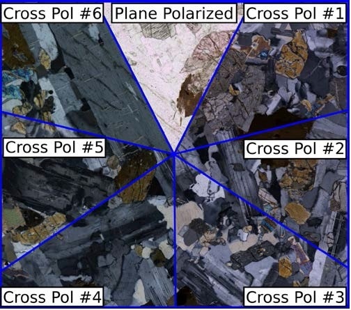
Figure 1. Multiple birefringence values exhibited by a single crystal at different polarization orientations. Image Credit: ZEISS Raw Materials Group
Technologies
To capture a stitched mosaic of high-resolution images over an area the size of a thin section typically necessitates application of reproducible scanning stage translating in X and Y. This preserves a suitable focus plane in Z. Such hardware is available, however, it presents a distinct challenge when paired with the requirement of viewing the sample in multiple orientations relative to the polarizer pair.
As described previously, a conventional petrographic microscope employs a fixed set of polarizers, oriented at 90 degrees to each other. An XY scanning stage lacks any rotational functionality, so a conventional microscope would only capture the sample at a single polarization orientation.
However, it is possible to acquire the relative rotation of the polarizer pair to the sample in the opposite manner, with a rotation of the polarizer-analyzer pair in relation to a fixed orientation sample on the XY scanning stage. This is made possible by employing a motorized polarizer and analyzer, and obtaining several data channels at regular orientations intervals (Figure 2).
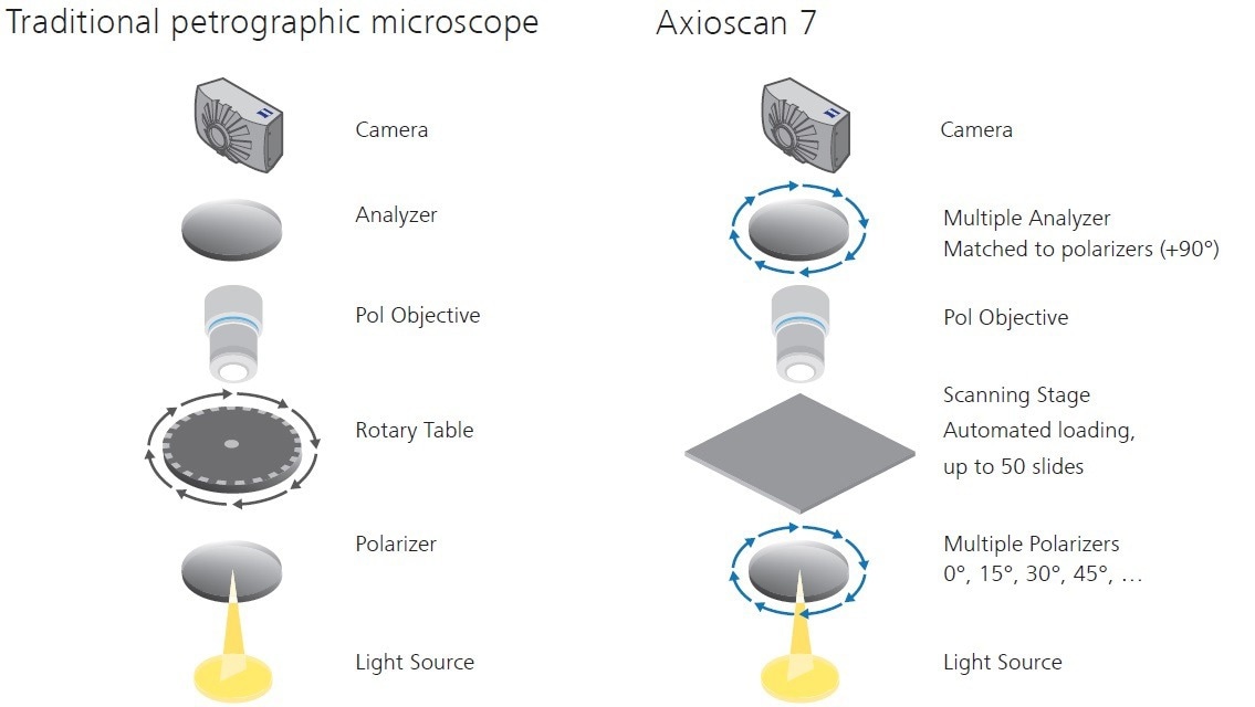
Figure 2. Digitization configuration for polarization microscopy. Image Credit: ZEISS Raw Materials Group
Each polarization channel acquired is then registered spatially with respect to one another, so that no spatial shifts are seen as the polarization orientation is changed.
This produces a correlated stack of cross-polarized images (multipol), each separated by a fixed angle (e.g. 15 degrees), that can be broken down into a digital equivalent of rotating the stage. This helps preserve most acquired data when using a conventional microscope.
While the multipol image stack mimics a conventional microscope, an easy way to optimize the information using a single image is via circular polarization. This condition is where two-quarter wave plates are inserted at 45 degrees into the polarizer and analyzer, respectively (Figure 3).
Birefringent crystals illuminated under such conditions demonstrate maximum birefringence, irrespective of their orientation relative to the polarizer-analyzer pair.
Circular polarization (c-pol) satisfies a different data analysis requirement than the multipol image stack. Utilizing a single cross-polarized image limits the data acquisition required, offering access to a novel method to distinguish phases.
For instance, in terms of digitization, employing light microscopy for image analysis and segmentation can be a trying process, as identical minerals in XPL can display varied birefringence or extinction, whereas c-pol has the advantage of exhibiting identical minerals in close alignment regardless of orientation across the sample (Figure 3).
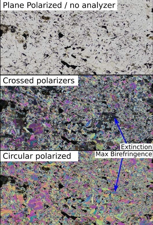
Figure 3. Circular polarized data shows maximum birefringence regardless of the relative orientation of the crystal and polarizer/analyzer pair. Image Credit: ZEISS Raw Materials
Therefore, the c-pol technique can work in combination with multipol depending on the requirements and workflows of the user. While c-pol offers an optimal image modality for digital image segmentation tasks, the rotational information in the multipol stack enables orientation of specific extinction angles in relation to neighboring grains and undulose extinction properties.
Pleochroism, or the color change in a mineral affiliated with changing polarizer orientation without an analyzer present (PPL), can be observed similarly to XPL, by obtaining multiple channels at various orientations of the polarizer with respect to the sample. Here, the maximum potential variation in color is observed over 180 degree (as opposed to 90 for birefringence) (Figure 4). The optical data can be acquired so that the PPL and XBL demonstrate complete correlation through the equivalent of a full-stage rotation.
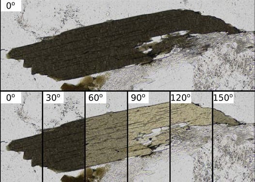
Figure 4. Pleochroism of biotite. As the orientation of the polarizer changes (without analyzer in place) mineral color changes. Image Credit: ZEISS Raw Materials Group
Multi-Channel Scanning and Registration
In general, digital imaging and large-scale sample digitization present a series of considerable challenges when compared to conventional microscopy. The relative spatial orientation of the multiple acquisition channels is important for computational image processing and analysis when being used to fully describe a sample.
The most straightforward of potential cases is that in between each acquisition, the illumination conditions are altered by modifying the equipment in the microscope’s optical path. However, this has the disadvantage that stage errors, compounded with shifts associated with variations in mosaic stitching algorithms, bring about significant shifts in apparent structure positions between channels.
While this may be acceptable during manual inspection, when performing computation processing and analysis on a stack of images, such shifts can alter resulting interpretations significantly (Figure 5).
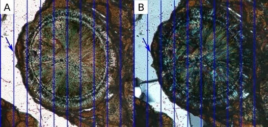
Figure 5. Channel shifts in multichannel data. Blue lines show the image grid with structures in plane polarized data (A) slightly to the left of cross polarized data (B). Image Credit: ZEISS Raw Materials Group
If access to an automated or motorized polarizer/analyzer is possible, the components in the microscope’s optical path in between each frame within the mosaic scan can be adjusted. This reduces the shift between individual image channels significantly, as there is no movement in the stage between channels during a single frame.
This is typically used with fluorescence microscopy in the life sciences, as various fluorescent stains are usually targeted at different functional objects. There is little to no mutual information between individual image channels.
As such, post-acquisition channel alignment presents a series of problematic challenges. However, this approach increases image acquisition time significantly, due to the need to switch components in the microscope in every frame within the mosaic (potentially thousands of individual images).
This method also leads to increased mechanical wear on the system (due to the large number of movements the system has to perform). It does not fully eliminate inter-channel shifts, as the various components introduced into the optical paths can provoke small apparent shifts, even if there is no movement in the sample or stage.
A final approach, of specific relevance to polarization, is the application of machine-learning techniques to register channels after acquisition. This is particularly useful for polarization microscopy, as each imaging configuration is, in effect, imaging the same structure. A significant amount of mutual information passes between channels (between brightfield and crossed polars, or different cross-polar orientations). This yields near-perfect registration between imaging channels (Figure 6) and exceptional quality computational image analysis.
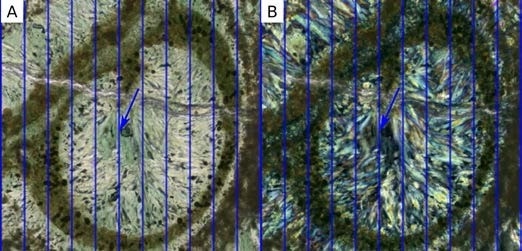
Figure 6. Multichannel acquisition with automated computer-vision based channel registration. Blue lines show the image grid. Image features are perfectly aligned between plane polarized (A) and cross polarized (B) channels. Image Credit: ZEISS Raw Materials
ZEISS Axioscan 7
The ZEISS Axioscan 7 is a complete digitization solution for polarization microscopy. It pairs high-throughput automated slide handling with novel imaging conditions to facilitate reliable, high-throughput digitization of geological samples. Up to 50 standard 1 in × 2 in, or 100 standard 25 mm × 75 mm geological samples can be loaded.
It uses simplified profile-based acquisition software, facilitating repetitive, consistent imaging. A motorized polarizer and analyzer are included, enabling examination of both birefringence and pleochroism. High-quality automated channel registration tools are also incorporated into data acquisition so that all tiles in a channel can be obtained without channel misalignment.
These features also facilitate the application of unique “line-scan” acquisition under brightfield, plane-polarized and cross-polarized conditions. In this acquisition mode, the sample is continuously moved, and static images are captured for a mosaic using a strobe to illuminate the sample rapidly. This is in contrast to conventional “stop and shoot” modes, where the sample is stopped before image capture, and the sample illumination uses conventional lighting.
This Axioscan 7 has the unique capacity to facilitate acquisitions up to 10 times faster than other conventional modes.

This information has been sourced, reviewed and adapted from materials provided by Carl Zeiss Microscopy GmbH.
For more information on this source, please visit Carl Zeiss Microscopy GmbH.