The time-dependent behavior of rocks is intimately connected to the stability and safety under buildings and tunnels. The study of the time-dependent behavior of rocks, also known as creep, is of special relevance in rock mechanics and the design of underground structures. This article looks at the development of a mathematical model for modeling rock time-dependent behavior described in Zohravi, S.E. et al.'s study published in the Journal of Civil Engineering and Management.
Image Credit: Anna Kucherova/Shutterstock.com
If the stress on the sample is high enough, the strain-versus-time curve normally contains three phases in the creep test: primary, secondary, and tertiary creep. To examine the time-dependent behavior of soils and rocks, many constitutive models have been proposed. General stress-strain models are often incremental and are regularly employed in the numerical methods-based analysis, thus they are suggested in engineering applications.
The over-stress theory of Perzyna is a broad theory for the elastic-visco-plastic behavior model of materials that predicts both time-dependent and time-independent behavior. This model, which is based on the moving yield surface idea, applies to any boundary conditions and stress trajectories. The yield function in moving yield surface theory is directly dependent on time and is constantly changing.
The sub-critical crack development model is one of the micro-mechanical damage models that are highly compatible with rock creep behavior. This model is particularly suited to the creep of rock materials because, as per this theory, microcrack formation is a time-dependent phenomenon that begins at a stress intensity factor smaller than the rock’s fracture toughness.
The goal of this article is to combine the stress hardening elastic-visco-plastic constitutive model with the damage criteria for sub-critical crack formation. The elastic-visco-plastic model is based on the over-stress hypothesis in general. It becomes a comprehensive model by incorporating the sub-critical crack development damage model, which replicates the creep behavior of the rock in both primary and secondary stages.
In most circumstances, the stress level is not high enough for the rock to enter the tertiary stage of creep. To put it another way, before the rock hits the tertiary stage of creep, the displacements rise to the point where the structure becomes unprofitable.
Various tests on a type of gypsum are used to calibrate the system. A comparison is conducted between the creep curve derived from the analytical-numerical model and the creep curve acquired from gypsum rock samples creep tests.
Methodology
The model given in this article is a mixture of elastic, plastic, and visco-plastic models based on Perzyna’s theory. In the principal stress space, Figure 1 depicts the overall shape of yield surfaces and the stress spaces between them. The visco-plastic yield surface and the perfect plastic yield surface are both treated in this model as yield surfaces with time-dependent behavior.
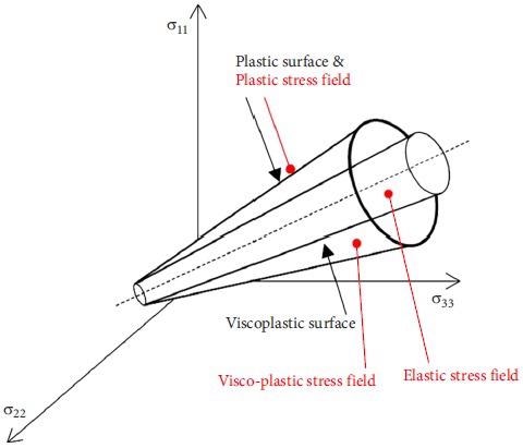
Figure 1. Visco-plastic and plastic yield surfaces in the principal stress space. Image Credit: Debernardi and Barla, 2009
Figure 2 illustrates the yield surface and spaces between the q-p plane. In Figure 2, σt denotes the rock’s tensile strength.
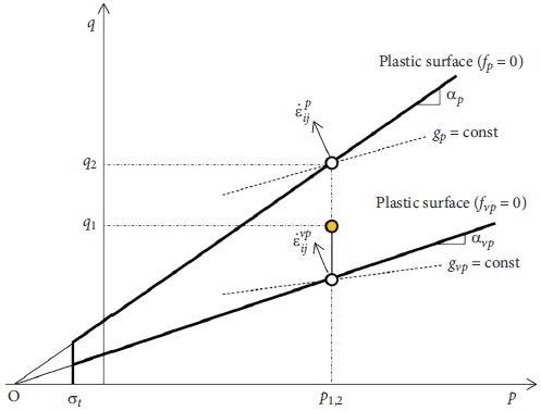
Figure 2. Yield surfaces and the spaces between them in the q-p coordinates. Image Credit: Debernardi and Barla, 2009
For sub-critical crack growth, Figure 3 depicts the crack velocity vs the normalized stress intensity factor.
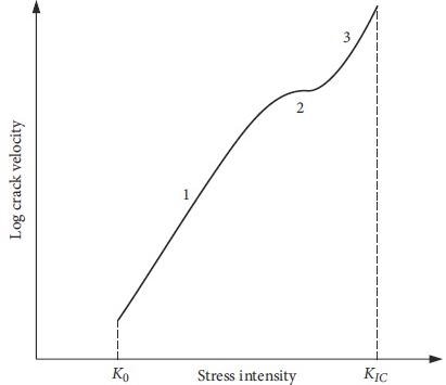
Figure 3. Experimental typical relationship between crack velocity and normalized stress intensity factor. Image Credit: Lockner and Madden, 1991
The application of compression loading on the sample generates frictional slides on the fault surfaces, resulting in the growth of wing fractures in the flaw tips (Figure 4).
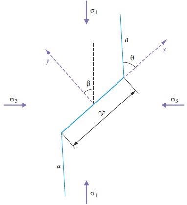
Figure 4. A flaw with the wing cracks at its tips. Image Credit: Zohravi, et al., 2022
The strain and stress relationships for each stage are supplied in the algorithm depicted in Figure 5.
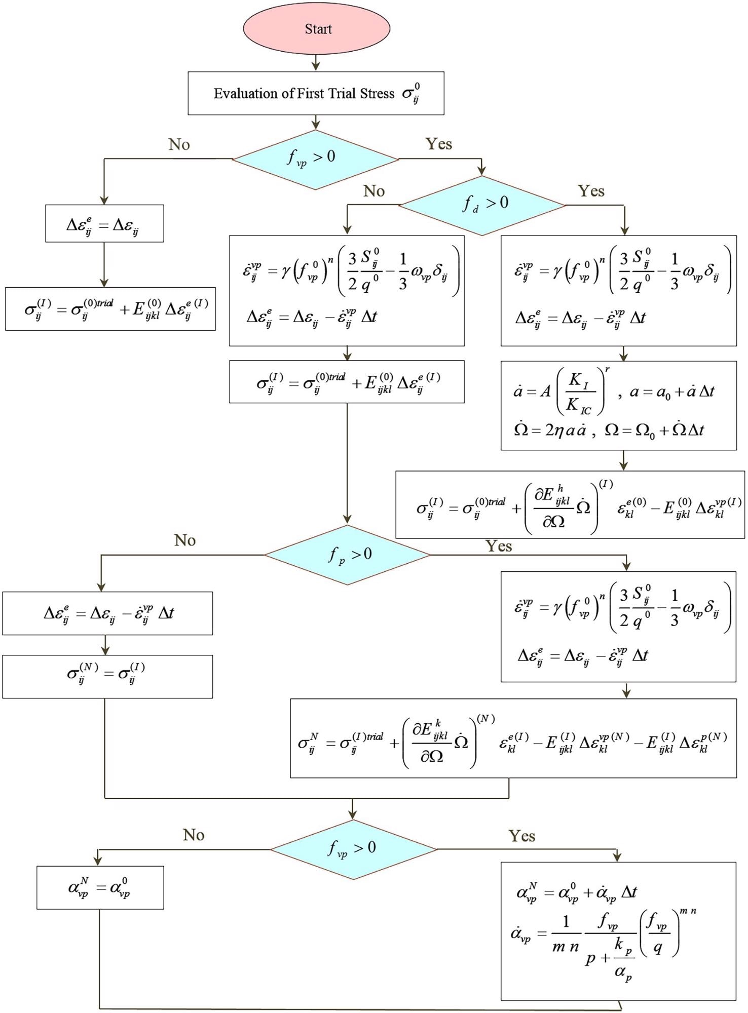
Figure 5. Computational algorithm of the mathematical model. Image Credit: Zohravi, et al., 2022
The results of the XRF test on this type of gypsum are shown in Table 1.
Table 1. XRF test result. Source: Zohravi, et al., 2022
| Mineral Oxides |
Weight (%) |
| Na2o |
0.03 |
| CaO |
32.2 |
| MgO |
0.01 |
| Fe2O3 |
0.05 |
| Al2O3 |
0.02 |
| SrO |
0.06 |
| SO3 |
46.06 |
| Loss on Ignition |
21.53 |
| Cl |
0.04 |
Elastic parameters (E, υ), the material’s elastic modulus, and Poisson’s ratio are calculated using the outcomes of uniaxial compression tests conducted on gypsum rock samples in line with the values in Table 2.
Table 2. Parameters of the model. Source: Zohravi, et al., 2022
| Parameter |
Index |
Unit |
Value |
| Elastic modulus |
E |
MPa |
33274 |
| Poisson’s ratio |
υ |
– |
0.271 |
| Slope of the Drucker-Pragers plastic yield surface in the q-p plane |
αp |
– |
0.788 |
| q-intercept of the Drucker- Pragers plastic yield surface |
kp |
MPa |
18.628 |
| Brazilian tensile strength |
σt |
MPa |
3.97 |
| Plastic dilatancy |
ωp |
– |
0 |
| Fluidity parameter |
γ |
– |
2.197e-8 |
| Shape factor |
m |
– |
1.002 |
| Load factor |
n |
– |
1.426 |
| Time stretching factor |
ℓ |
– |
79.295 |
| Visco-plastic dilatancy |
ωvp |
– |
0.012 |
| Fracture toughness (mode I) |
KIc |
MPa√m |
0.612 |
| Sub-critical crack growth parameter |
A |
m/s |
0.5 |
| Sub-critical crack growth index |
r |
– |
25 |
| Flaw density |
η |
m–2 |
4.26E9 |
| Flaw size |
2s |
μm |
150.6 |
| Flaw orientation |
β |
(°) |
45 |
| Coefficient of friction on the flaw surface |
μ |
– |
0.2 |
Result
In a uniaxial creep test, the suggested constitutive model is combined with the sub-critical crack growth model. Only a fourth of the specimen in the test is modeled according to the symmetry criteria of the specimen (Figure 6).
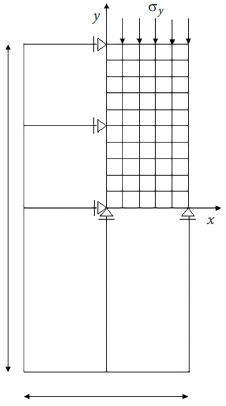
Figure 6. Loading and boundary conditions for a quarter of the model. Image Credit: Zohravi, et al., 2022
Figure 7 illustrates the damage parameter’s evolution as a function of loading time. Figure 8 depicts the lengthening of the wing fracture over time.
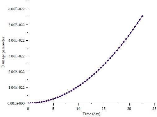
Figure 7. Evolution of damage parameter with time. Image Credit: Zohravi, et al., 2022
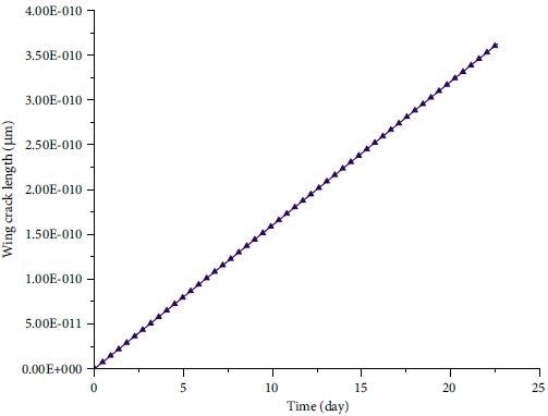
Figure 8. Evolution of wing crack length with time. Image Credit: Zohravi, et al., 2022
Figure 9 depicts the variations in the KI / KIc ratio as a function of time; as can be observed, this ratio drops somewhat over the loading period, accompanied by a constant and progressive rise in wing crack length. Figure 10 compares the creep curve acquired from laboratory data to the theoretical-numerical model's fitted curve.
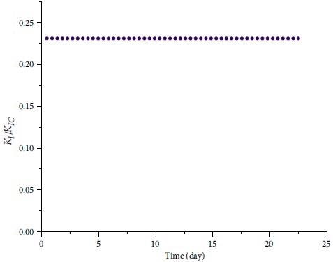
Figure 9. Evolution of normalized stress intensity factor versus time. Image Credit: Zohravi, et al., 2022
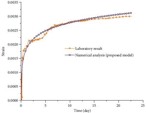
Figure 10. Creep curves, comparison between the results obtained from the laboratory data with the fitted curve of the proposed model. Image Credit: Zohravi, et al., 2022
Conclusion
A mathematical model for modeling rock time-dependent behavior is described in this study. The suggested model is a hybrid of an elastic-visco-plastic model and the stress hardening law, based on Perzyna’s over-stress theory. A micro-mechanical damage model is used to study damage during creep. Wing fractures emerge at the tips of faults that are equally distributed in the material, according to the micro-mechanical damage model.
Before the stress intensity factor reaches a crucial value, wing cracks begin to form. The strain and damage parameters rise as wing fractures widen during creep. It was discovered that the creep curve obtained from the laboratory findings is in good agreement with the fitted creep curve of the theoretical-numerical model after defining the model parameters and calibration using tests on gypsum samples.
According to the research results, the length of the wing crack and the failure parameter increase during the primary and secondary stages of creep. The rate of increase of wing crack length is constant in both stages of creep testing, but the rate of increase of damage parameter is higher in the secondary stage than the primary stage.
Journal Reference
Zohravi, S.E., Lakirouhani, A., Molladavoodi, H., Medzvieckas, J. and Kliukas, R., (2022). A new constitutive model for the time-dependent behavior of rocks with consideration of damage parameter. Journal of Civil Engineering and Management, 28(3), pp.223-231. Available Online: https://journals.vgtu.lt/index.php/JCEM/article/view/16609/11057.
References and Further Reading
- Afrouz, A & Harvey, J M (1974) Rheology of rocks within the soft to medium strength range. International Journal of Rock Mechanics and Mining Sciences &Geomechanics Abstracts, 11, pp. 281–290. doi.org/10.1016/0148-9062(74)90230-7.
- Ashby, M F & Hallam, S D (1986) The failure of brittle solids containing small cracks under compressive stress states. ActaMetallurgica, 34(3), pp. 497–510. doi.org/10.1016/0001-6160(86)90086-6.
- Aydan, Ö (2016) Time-dependency in rock mechanics and rock engineering (1st ed.). CRC Press. doi.org/10.1201/9781315375151.
- Aydan, Ö., et al. (2014) ISRM suggested methods for determining the creep characteristics of rock. Rock Mechanics and Rock Engineering, 47(1), pp. 275–290. doi.org/10.1007/s00603-013-0520-6.
- Debernardi, D &Barla, G (2009) Newviscoplastic model for design analysis of tunnels in squeezing conditions. Rock Mechanics and Rock Engineering, 42(2), p. 259. doi.org/10.1007/s00603-009-0174-6.
- Feng, W., et al. (2020). An improved nonlinear damage model of rocks considering initial damage and damage evolution. InternationalJournal of Damage Mechanics, 29, pp. 1117–1137. doi.org/10.1177%2F1056789520909531.
- Gioda, G &Cividini, A (1996) Numerical methods for the analysis of tunnel performance in squeezing rocks. Rock Mechanics and Rock Engineering, 29(4), pp. 171–193. doi.org/10.1007/BF01042531.
- Goodman, R E (1989). Introduction to rock mechanics (2nd ed.) John Wiley & Sons Ltd.
- Griggs, D T & Coles, N E (1954) Creep of single crystals of ice (SIPRE Report, 11). U.S. Army Snow, Ice, and PermafrostResearch Establishment.
- Gross, D &Seelig, T (2018) Fracture mechanics: With an introduction to micromechanics (3rd ed.) Springer. doi.org/10.1007/978-3-319-71090-7.
- Hasanzadehshooiili, H., et al. (2012) Evaluating elastic-plastic behaviour of rock materials using hoek–brown failure criterion. Journal of Civil Engineering and Management, 18(3), pp. 402–407. doi.org/10.3846/13923730.2012.693535.
- Horii, H &Nemat-Nasser, S (1986) Brittle failure in compression: splitting faulting and brittle-ductile transition. Philosophical Transactions of the Royal Society of London. Series A, Mathematical and Physical Sciences, 319, pp. 337–374. doi.org/10.1098/rsta.1986.0101.
- Hou, R., et al. (2019) A nonlinear creep damage coupled model for rock considering the effect of initial damage. Rock Mechanics and Rock Engineering,52(5), pp. 1275–1285. doi.org/10.1007/s00603-018-1626-7.
- Huang, M., et al. (2020) New creep constitutive model for soft rocks and its application in the prediction of time-dependent deformation in tunnels. InternationalJournal of Geomechanics, 20(7), p. 04020096. doi.org/10.1061/(ASCE)GM.1943-5622.0001663.
- Itasca Consulting Group, Inc. (2019). FLAC—Fast Lagrangian analysis of continua (Ver. 8.1). Itasca.
- Kemeny, J (1991) A model for non-linear rock deformation under compression due to sub-critical crack growth. InternationalJournal of Rock Mechanics and Mining Sciences &Geomechanics Abstracts, 28, pp. 459–467. doi.org/10.1016/0148-9062%2891%2991121-7.
- Ko, T. Y., et al. (2006) Crack coalescence in brittle material under cyclic loading. In Proceedings of the the41st U.S. Rock Mechanics Symposium (Paper ARMA 06-930).Golden, CO.
- Ko, T Y &Kemeny, J (2013) Determination of the subcritical crack growth parameters in rocks using the constant stress at test. International Journal of Rock Mechanics and MiningSciences, 59, pp. 166–178. doi.org/10.1016/j.ijrmms.2012.11.006.
- Ko, T Y & Lee, S S (2020) Characteristics of crack growth in rock-like materials under monotonic and cyclic loading conditions. Applied Sciences, 10(2), p. 719. doi.org/10.3390/app10020719.
- Kranz, R L (1979) Crack growth and development during creep of Barre granite. International Journal of Rock Mechanics and Mining Sciences &Geomechanics Abstracts, 16(1), pp. 23–35. doi.org/10.1016/0148-9062(79)90772-1.
- Kranz, R L (1980) The effects of confining pressure and stress difference on static fatigue of granite. Journal of Geophysical Research: Solid Earth, 85(B4), pp. 1854–1866. doi.org/10.1029/JB085iB04p01854.
- Lakirouhani, A &Hasanzadehshooiili, H (2011). Review of rock strength criteria. In Proceedings of the 22nd World MiningCongress & Expo, pp. 473–482. Istanbul, Turkey.
- Lemaitre, J &Chaboche, J (1990) Mechanics of solid materials. Cambridge University Press. doi.org/10.1017/CBO9781139167970.
- Lockner, D (1993) Room temperature creep in saturated granite. Journal of Geophysical Research: Solid Earth, 98(B1), pp. 475–487. doi.org/10.1029/92JB01828.
- Lockner, D A & Madden, T R (1991) A multiple-crack model of brittle fracture: 2. Time-dependent simulations. Journal of Geophysical Research: Solid Earth, 96(B12), pp. 19643–19654. doi.org/10.1029/91JB01641.
- Lomnitz, C (1956) Creep measurements in igneous rocks. TheJournal of Geology, 64(5), pp. 473–479. doi.org/10.1086/626379.
- Ma, L., et al. (2017). A variable parameter creep damage model incorporating the effects of loading frequency for rock salt and its application in a bedded storage cavern. Rock Mechanics and Rock Engineering, 50, p. 2495. doi.org/10.1007/s00603-017-1236-9.
- Paliwal, B & Ramesh, K T (2008). An interacting micro-crack damage model for failure of brittle materials under compression.Journal of the Mechanics and Physics of Solids, 56(3),pp. 896–923. doi.org/10.1016/j.jmps.2007.06.012.
- Olson, J (1993). Joint pattern development: Effects of subcritical crack growth and mechanical crack interaction. Journal of Geophysical Research, 98, pp. 12251–12265. doi.org/10.1029/93JB00779.
- Pellet, F., et al. (2005) A viscoplastic model including anisotropic damage for the time dependent behaviour of rock. International Journal for Numerical and Analytical Methods in Geomechanics, 29(9), pp. 941–970. doi.org/10.1002/nag.450.
- Perzyna, P (1966) Fundamental problems in viscoplasticity. Advances in Applied Mechanics, 9, pp. 246–377. doi.org/10.1016/S0065-2156(08)70009-7.
- Robertson, E C (1955) Experimental study of the strength of rocks. GSA Bulletin, 66(10), pp. 1275–1314.doi.org/10.1130/0016-7606(1955)66[1275:ESOTSO]2.0.CO;2.
- Shao, JF., et al. (2006) Modeling of anisotropic damage and creep deformation in brittle rocks. InternationalJournal of Rock Mechanics and Mining Sciences, 43, pp. 82–592. doi.org/10.1016/j.ijrmms.2005.10.004.
- Sterpi, D &Gioda, G (2009) Visco-plastic behaviour around advancing tunnels in squeezing rock. Rock Mechanics and Rock Engineering, 42(2), pp. 319–339. doi.org/10.1007/s00603-007-0137-8.
- Zhang, J. Z., et al. (2019) Visco-plastic deformation analysis of rock tunnels based on fractional derivatives. Tunnelling and Underground Space Technology, 85, pp. 209–219. doi.org/10.1016/j.tust.2018.12.019.