Belt conveyors transport raw materials over long distances within mines (up to several dozens of km). They are usually in operation nearly 24 hours a day, often in hostile environments, such as underground mines.
Belt conveyors are obviously subjected to faster decomposition processes. They should be inspected on a regular basis according to mining law and enterprise internal regulations.
Normally, SCADA systems are used to monitor some conveyor elements (drive units) 24 hours a day. Maintenance personnel inspects the rest of the conveyor. This necessitates a visual inspection of all elements along the conveyor to look for anomalies (see Figure 1).
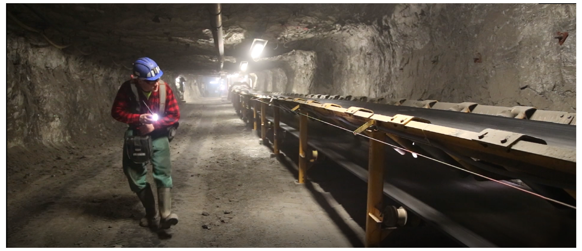
Figure 1. Conveyor belt route inspection in traditional form. Image Credit: Szrek, et al., 2022
Conveyors, on the other hand, require a lot of power and are spread out over a large area. Mining companies are looking for new ways to keep conveyors in good working order. Several research groups have already developed inspection robots for mining applications.
However, due to issues such as localization and navigation, using inspection robots in the mine is difficult. This has been tested using unmanned ground vehicles (UGVs), unmanned aerial vehicles (UAVs), and walking robots. Underground mines are not suitable for UAVs due to the powder/dust conditions.
Furthermore, when compared to UGVs, legged robots are far more complex. As a result, a UGV appears to be the best option for application in terms of payload, speed, battery consumption, and stability.
Researchers have proposed a mobile inspection platform based on autonomous UGVs to reduce the presence of humans in a harsh mining environment. It is equipped with a variety of sensors (RGB image, gas sensor, and sound) and can collect nearly the same data as a maintenance vehicle. They also highlight some research challenges, particularly for planned validation in underground mines.
Methodology
The goal of this research is to conduct automated inspection missions to aid in the daily maintenance of mine belt conveyors. Because field experiments in deep mines are difficult to organize, are expensive, and there is a finite amount of time to test/validate the system, a belt conveyor test rig intended for research purposes (see Figure 2) was used in the study.
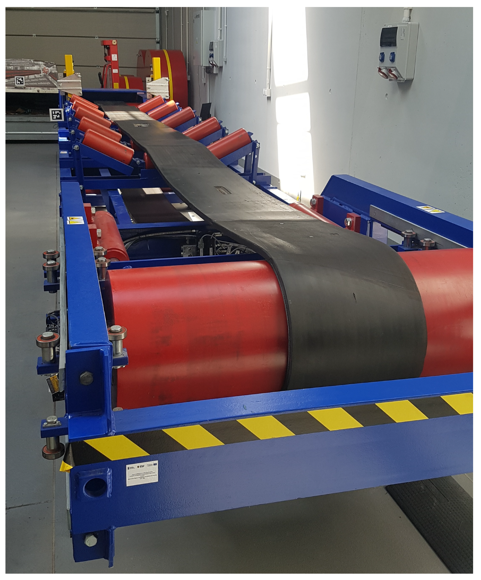
Figure 2. Belt conveyor system in the lab. Image Credit: Szrek, et al., 2022
As a reference for experiments, a point cloud map of the lab was gathered using a high-resolution stationary geodesic LIDAR (Figure 3).
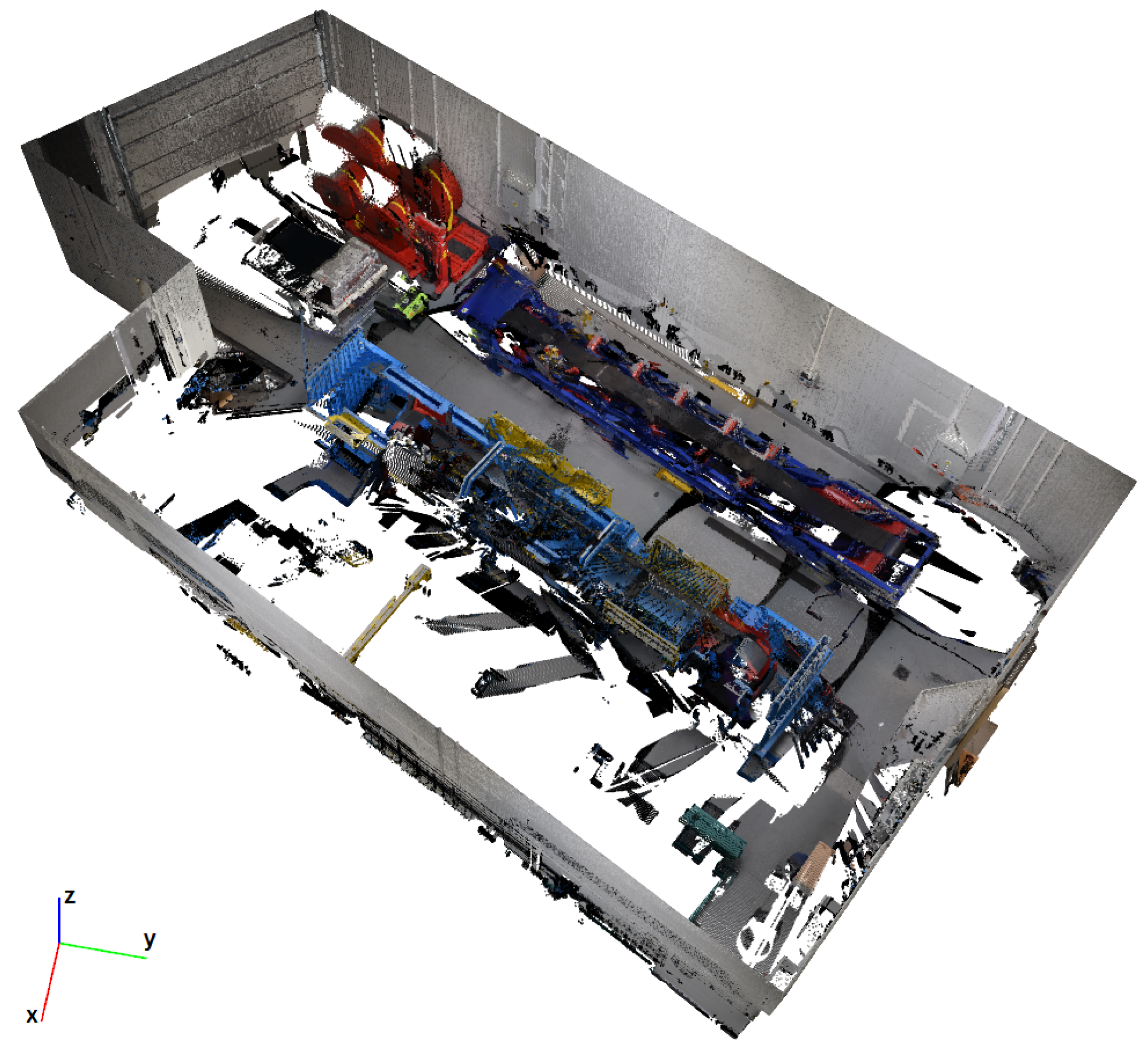
Figure 3. Reference point cloud of the inspected area. Image Credit: Trybała, et al., 2021
After analyzing the requirements of the automatic inspection process, it was split into two parts: inspection planning and inspection execution.
In the first part, the inspection procedure is broken down into simple tasks for the robot, such as defining paths to be pursued and measurements to be taken at specific locations.
The study proposes an automated inspection procedure. Furthermore, a system was created to substantiate the procedure in laboratory conditions, including its components and functions. Figure 4 depicts the facility’s general layout, with the relevant areas for the inspection mission’s planning highlighted.
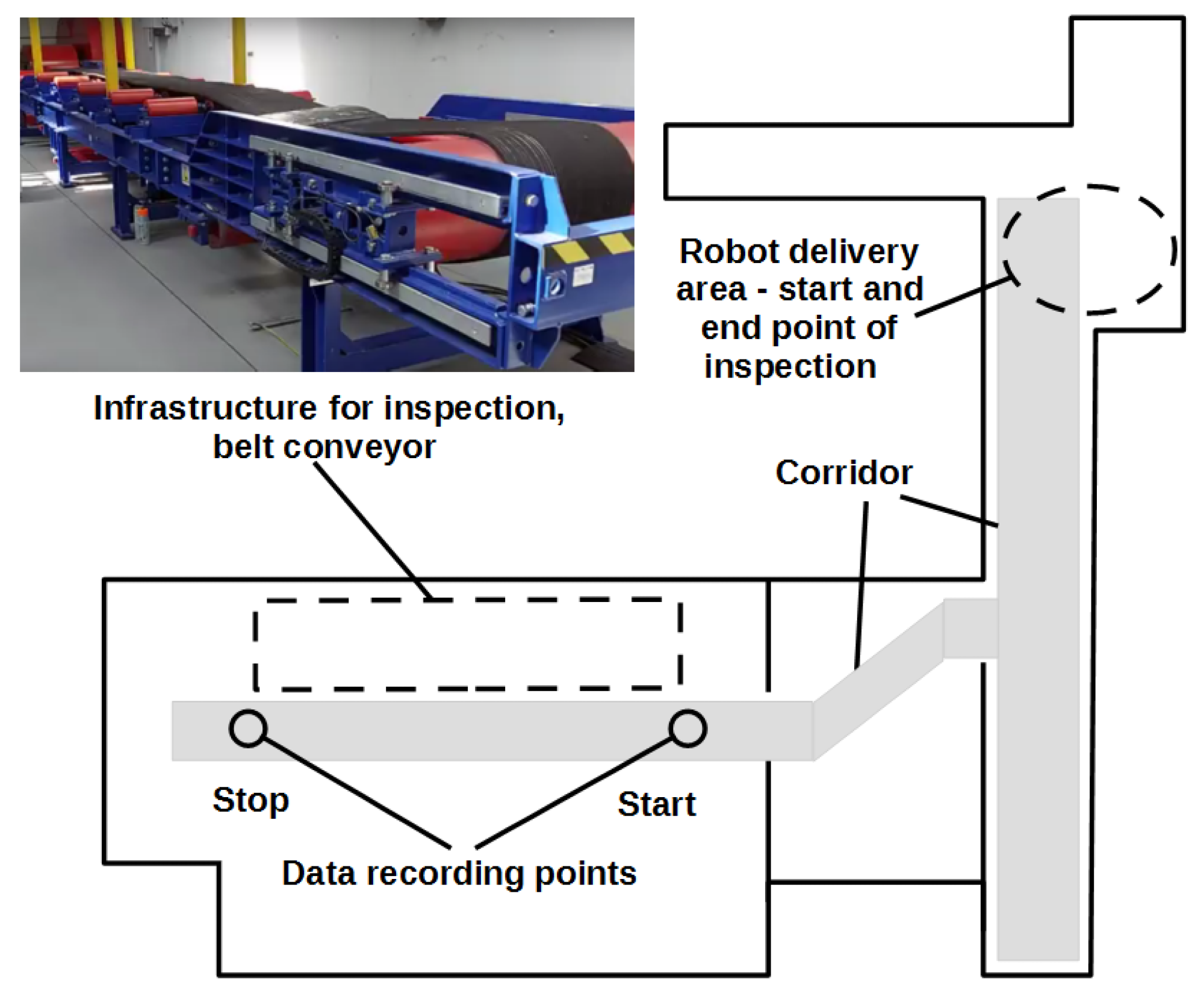
Figure 4. Inspection area layout. Image Credit: Szrek, et al., 2022
The UGV platform components are depicted in Figure 5.
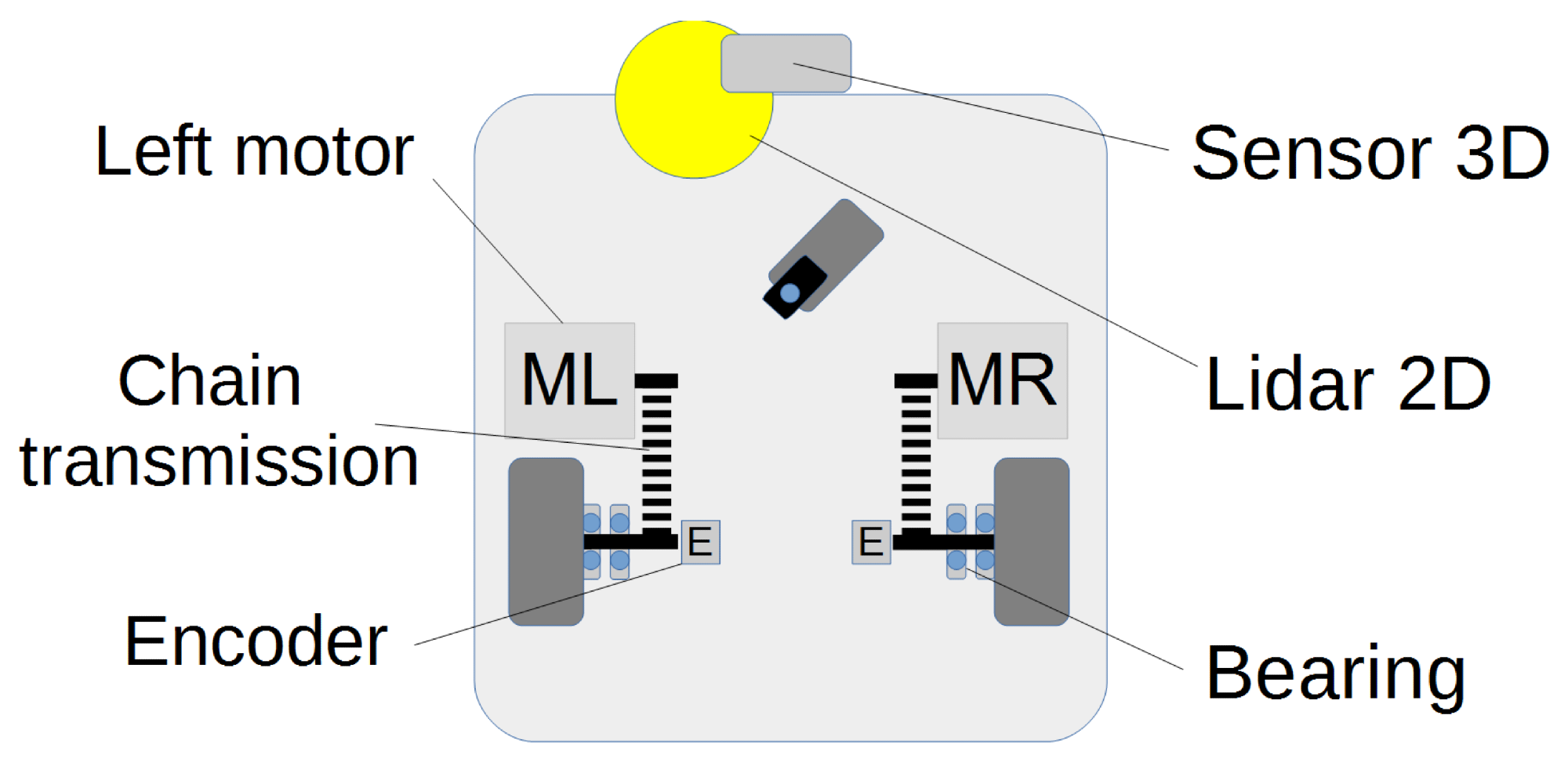
Figure 5. Placement of relevant robot components. Image Credit: Szrek, et al., 2022
The mobile platform is made up of a rigid body with wheels attached to it. Figure 6 depicts the space in which the robot will be described.
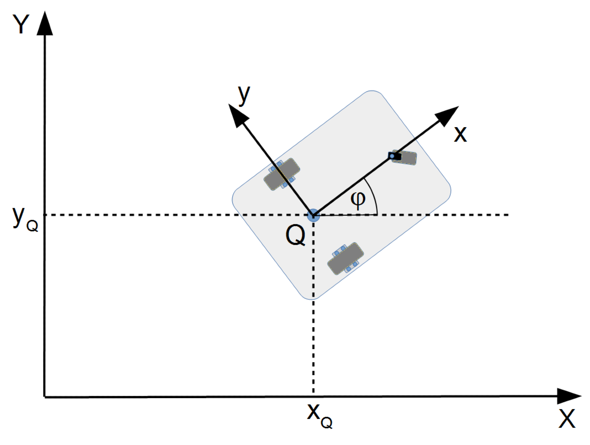
Figure 6. Global and local coordinates of the mobile robot. Image Credit: Szrek, et al., 2022
Geometric parameters, as shown in Figure 7, are required for a detailed description of the platform movement. Figure 7 depicts the instantaneous center of rotation around which the platform rotates.
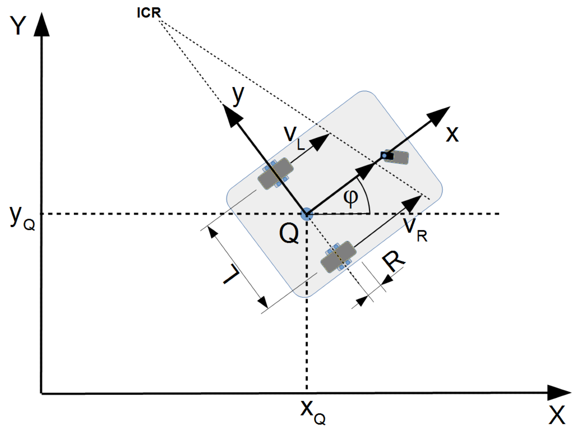
Figure 7. Parameters of the mobile robot. Image Credit: Szrek, et al., 2022
The mobile platform’s kinematic model has natural input parameters, including linear and angular velocity, and is used in algorithms such as trajectory planning. Figure 8 depicts the platform control system as a block diagram.
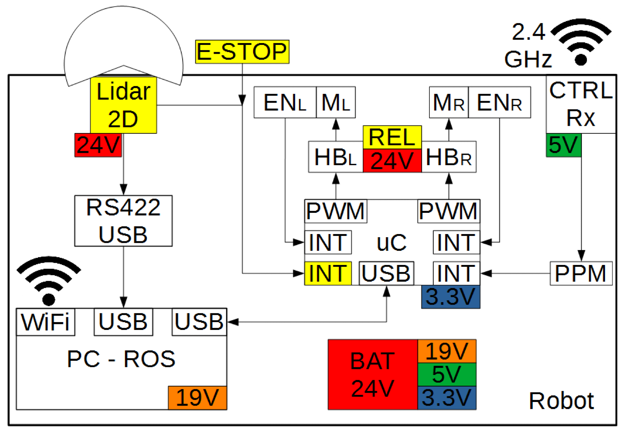
Figure 8. Control system of the mobile robot. Image Credit: Szrek, et al., 2022
In either manual or autonomous mode, the robot can be controlled. The RC transmitter is used to switch between modes remotely. The WiFi network generated by the robot’s computer can also be used to remotely view the robot’s current state (Figure 9).
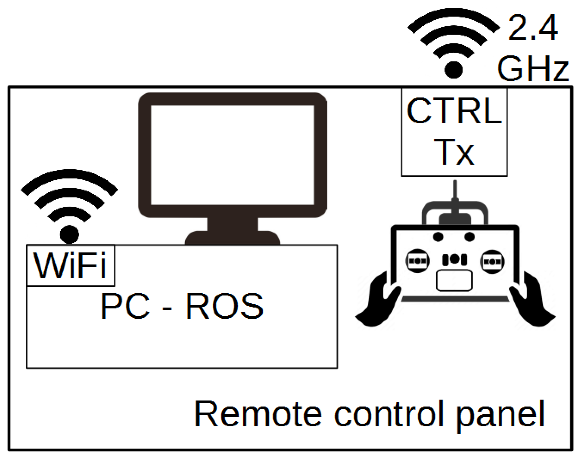
Figure 9. The remote control panel of mobile robot. Image Credit: Szrek, et al., 2022
The Robot Operating System (ROS) framework is used to control the platform’s navigation. The system’s architecture is depicted in Figure 10.
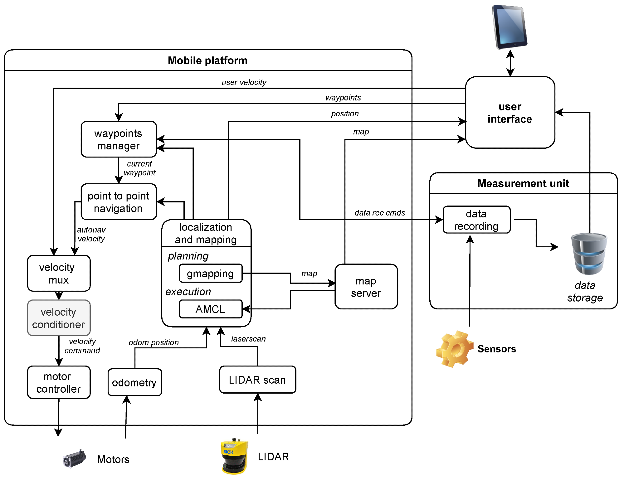
Figure 10. Software components of the system and data flow. Image Credit: Szrek, et al., 2022
Mapping and localization, autonomous navigation, and motion execution are the three main logical subsystems in the architecture.
Localization and mapping tasks can be solved simultaneously or separately as a Simultaneous Localization And Mapping (SLAM) problem. The researchers decided to take a hybrid approach to this system. They used full SLAM in the planning phase. The “mapping and localization” block illustrates this difference in behavior.
Communication between functional program modules is governed by the MQTT protocol. A request is made to begin data logging when the inspection start point is reached (see Figure 11). The module in charge of registration sends a confirmation message after initializing the measurement system and saving the data. The maximum waiting time for confirmation messages has been set to secure the measurement system.
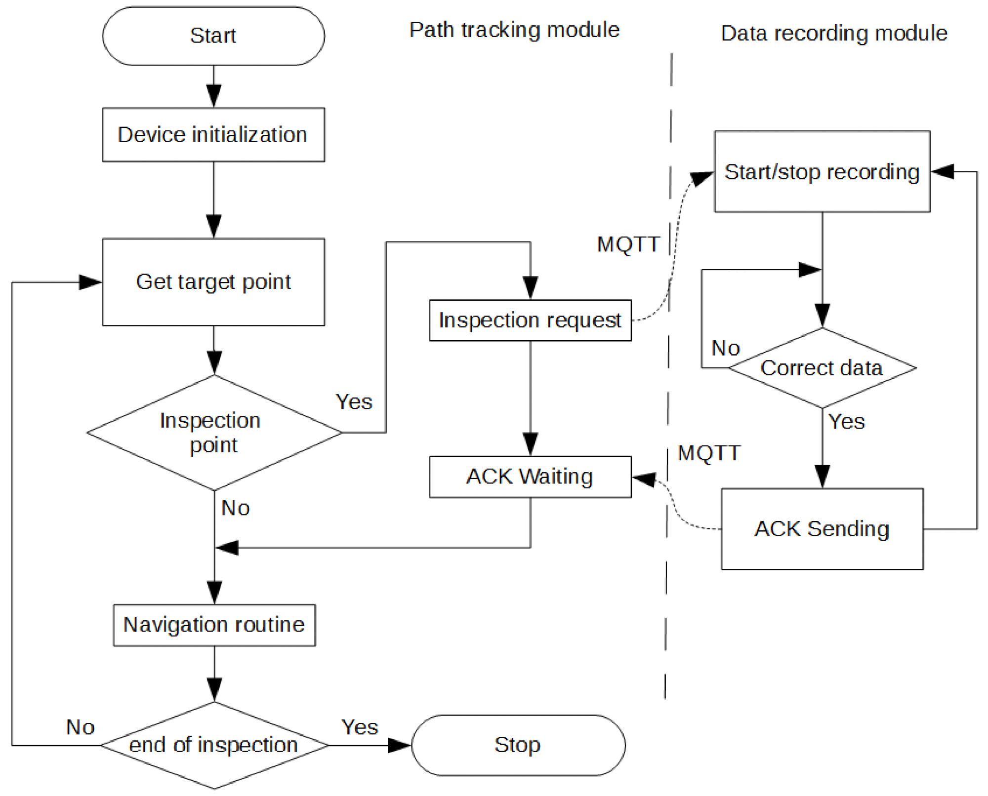
Figure 11. Inspection algorithm and data flow. Image Credit: Szrek, et al., 2022
Results and Discussion
Figure 4 depicted a visual description of the mission, and Figure 12 illustrates the map of the area with points of interest.
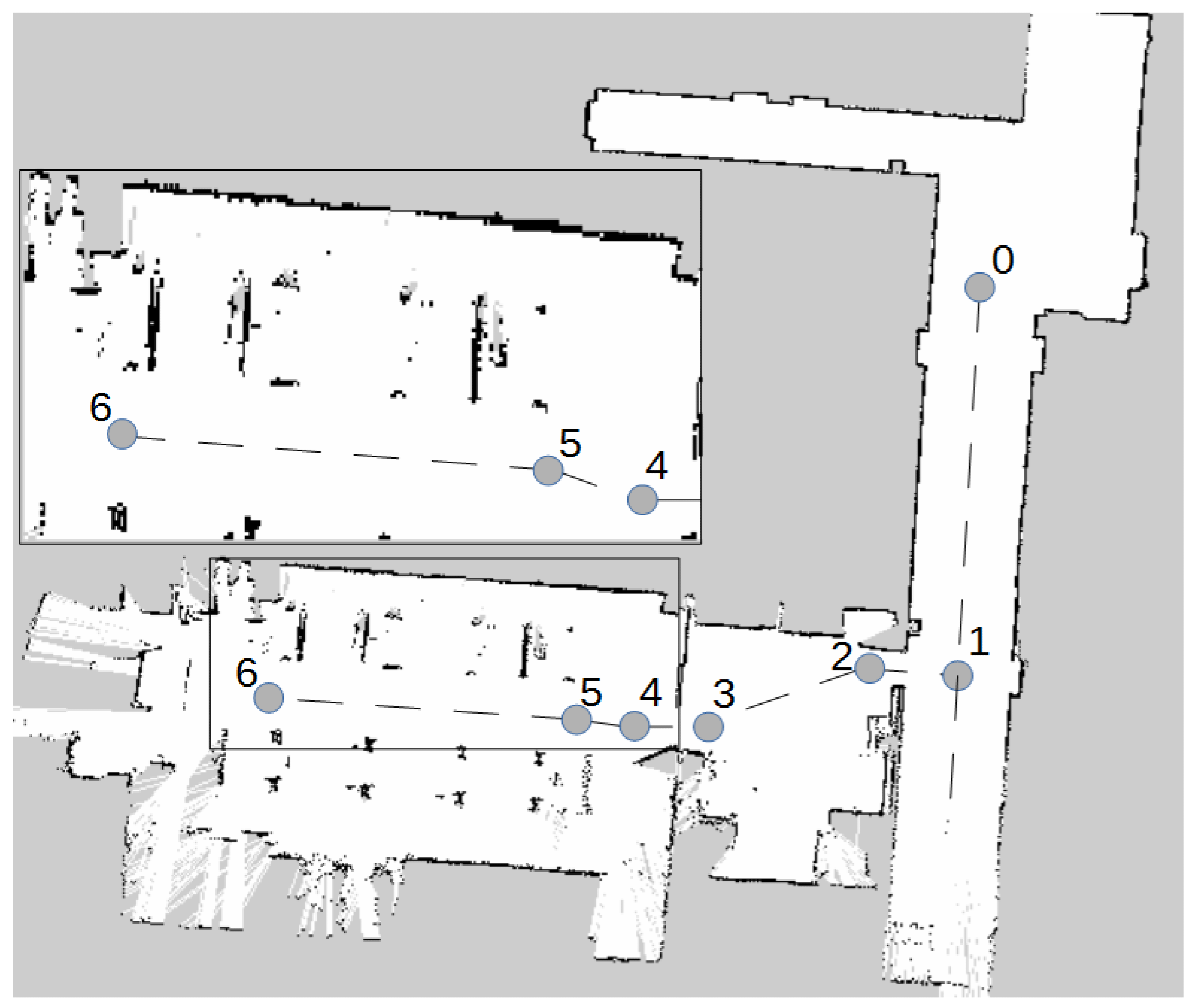
Figure 12. Map of the area with points of interest. Image Credit: Szrek, et al., 2022
During a remotely controlled run, the experiment area was mapped. A 2D LIDAR was used to register area boundaries and obstacles for the laboratory experiments. The image data of the conveyor was recorded to ensure proper communication with the measurement system. The experiment was run several times with two different forward velocity limits. Figure 13 depicts the view of the conveyor belt during the experiments.
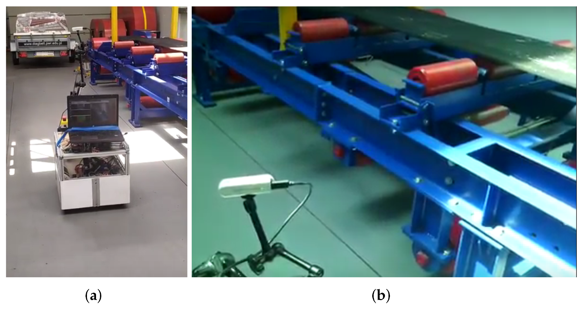
Figure 13. An inspection robot during the experiment: (a) general photo; (b) zoom on sensor. Image Credit: Szrek, et al., 2022
Figure 14 shows the results in time series plots for both slow and fast passes. However, in the majority of the experiments, the path did not deviate from the plan by more than ±0.02 m.
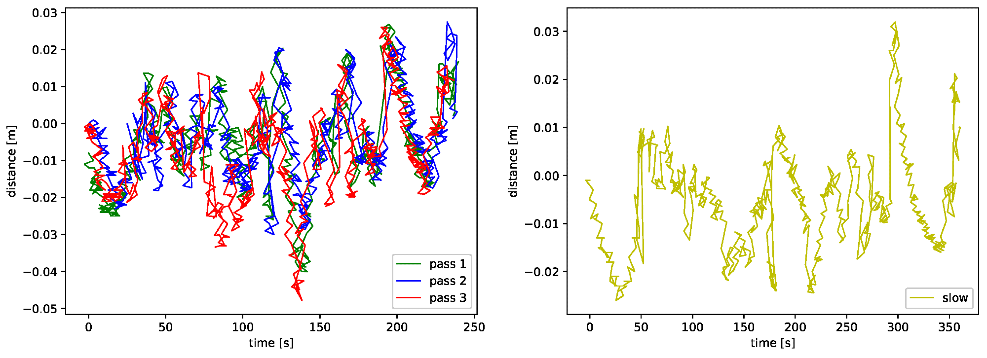
Figure 14. Displacement from the plan and the traveled paths in fast (left) and slow (right) passes. Image Credit: Szrek, et al., 2022
Figure 15 shows a visual comparison of “fast” paths and the planned path.
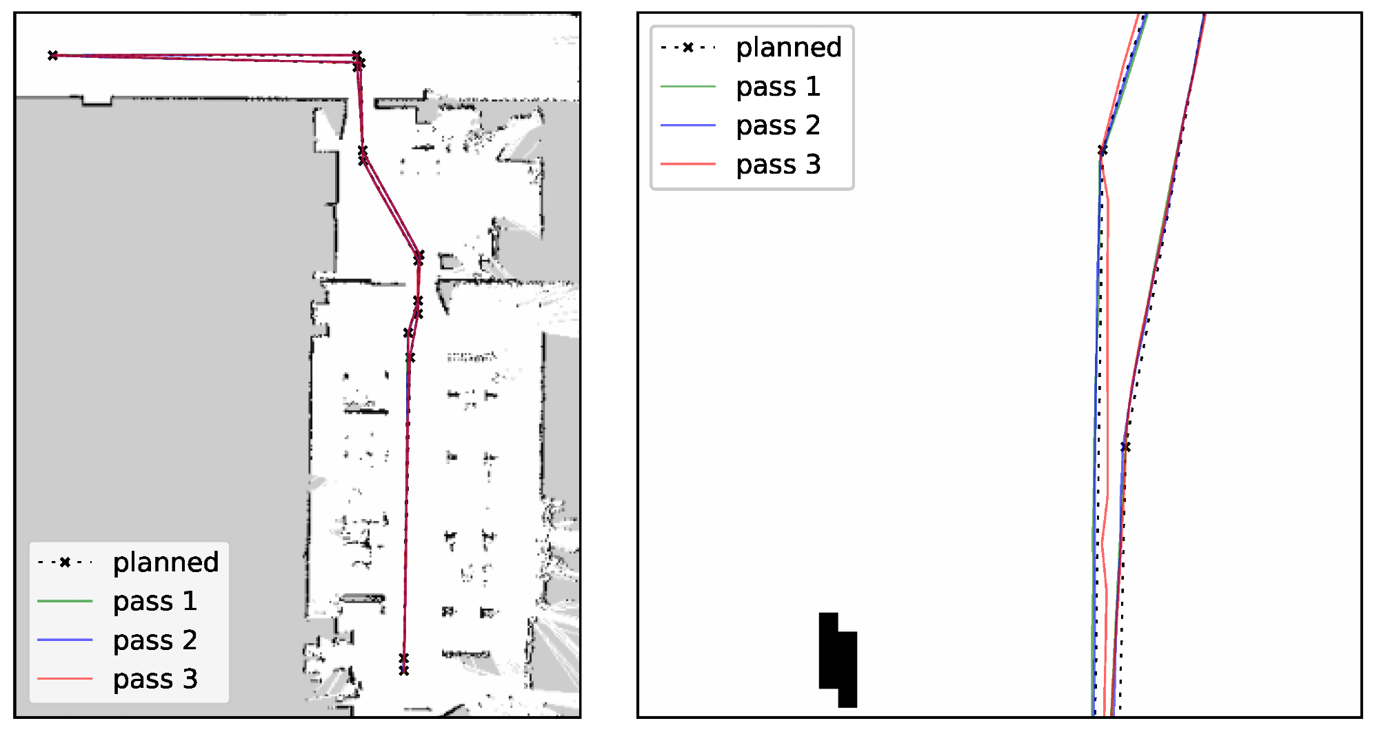
Figure 15. Paths: planned and the traveled in passes 1 to 3—whole path and a zoom-in. Image Credit: Szrek, et al., 2022
Figure 16 depicts a similar comparison between one of the “slow” passes and one of the “fast” passes. The findings indicate that the paths are repeatable and that lowering the velocity did not improve the quality of the path following significantly.
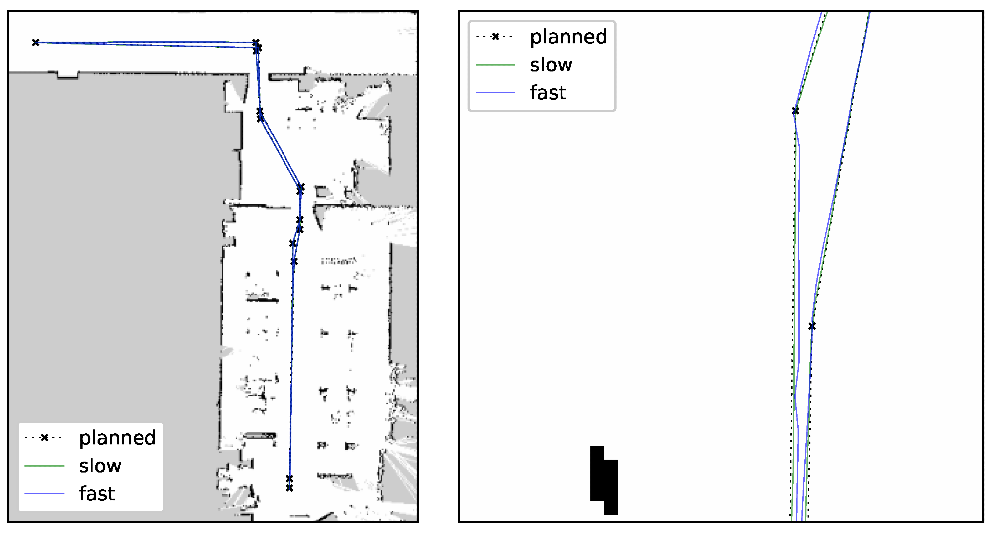
Figure 16. Comparison of planned and traveled paths in a slow and a fast pass—whole path and a zoom-in. Image Credit: Szrek, et al., 2022
The results of all tests indicate that the AMCL localization was implemented well enough for navigation. Figure 17 displays the results of all passes. The results are less repeatable than in the AMCL case.
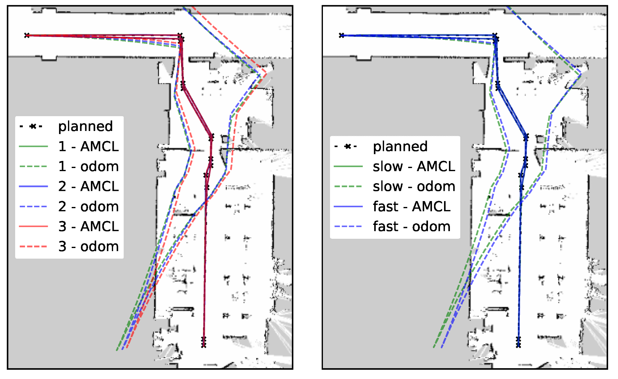
Figure 17. Comparison of localization from AMCL and odometry—passes 1 to 3 (left) and fast vs. slow (right). Image Credit: Szrek, et al., 2022
Using RTABMap, a 3D map was also created during the inspection drive, which is shown in Figure 18. The visualization of the robot’s path during the space experiment is shown in the figure.
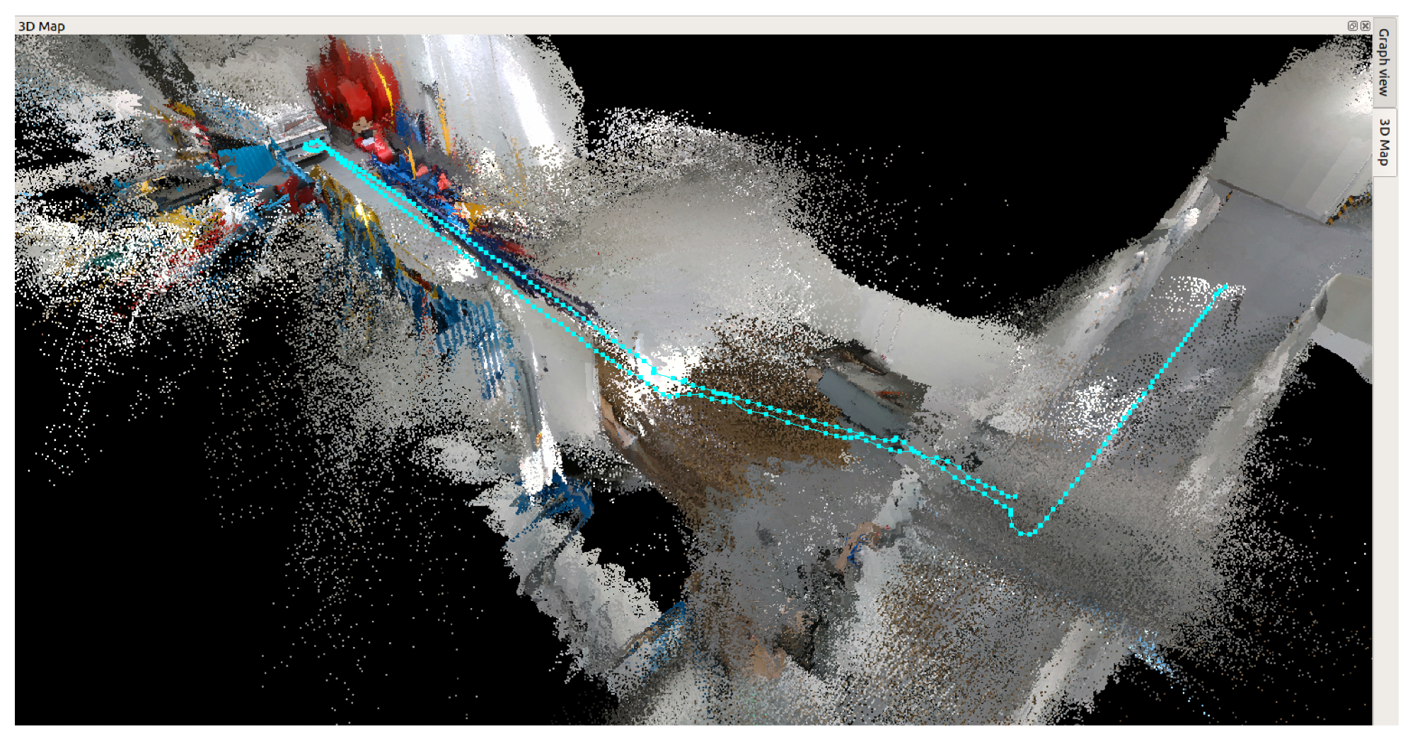
Figure 18. 3D map made during the autonomous driving with the robot’s path. Image Credit: Szrek, et al., 2022
Conclusion
The current study proposes an architecture for an automated inspection system of technical infrastructures such as belt conveyors using a mobile robot platform, as well as a procedure for performing such inspections. Experiments in a laboratory environment were used to verify the system’s correct operation. The laboratory tests were conducted to ensure that the system can complete the entire scheduled inspection route without the intervention of an operator.
The concept of the system has been proven by the results of laboratory tests. The next step in the research is to introduce the tests in real-world scenarios. That will necessitate extending the current solution, which relies on a 2D map, to include the ability to move on rough (uneven) terrain, which will necessitate the use of either a full spatial map or multi-layer 2D maps.
Journal Reference:
Szrek, J., Jakubiak, J., Zimroz, R. et al. (2022) A Mobile Robot-Based System for Automatic Inspection of Belt Conveyors in Mining Industry. Energies, 15(1), p. 327. Available Online: https://www.mdpi.com/1996-1073/15/1/327/htm.
References and Further Reading
- Bulk Solid Handlings (2020).
- Popescu, F (2008) Controls ways of the transportation capacity variation for the canvas conveyer. WSEAS Transactions on Systems and Control, 3, pp. 393–402.
- Hebda-Sobkowicz, J., et al. (2019) Pattern of H2S concentration in a deep copper mine and its correlation with ventilation schedule. Measurement, 140, pp. 373–381. doi.org/10.1016/j.measurement.2019.03.077.
- Hebda-Sobkowicz, J., et al. (2019) Identification and Statistical Analysis of Impulse-Like Patterns of Carbon Monoxide Variation in Deep Underground Mines Associated with the Blasting Procedure. Sensors, 19, p. 2757. doi.org/10.3390/s19122757.
- Polish State Mining Authority (2021). Available at: https://www.wug.gov.pl/bhp/stan_bhp_w_gornictwie
- Grzesiek, A., et al. (2020) Long term belt conveyor gearbox temperature data analysis–Statistical tests for anomaly detection. Journal of the International Measurement Confederation, 165, p. 108124. doi.org/10.1016/j.measurement.2020.108124
- Błazej, R., et al. (2016) Automatic analysis of thermograms as a means for estimating technical of a gear system. Diagnostyka, 17, pp. 43–48.
- Doroszuk, B & Król, R (2019) Analysis of conveyor belt wear caused by material acceleration in transfer stations. Mining Science, 26, pp. 189–201. doi.org/10.37190/msc192615
- Wozniak, D & Hardygora, M (2020) Method for laboratory testing rubber penetration of steel cords in conveyor belts. Mining Science, 27, pp. 105–117. doi.org/10.37190/msc202708
- Trybała, P., et al. (2021) Damage Detection Based on 3D Point Cloud Data Processing from Laser Scanning of Conveyor Belt Surface. Remote Sensing, 13, p. 55. doi.org/10.3390/rs13010055.
- Kozłowski, T., et al. (2020) diagnostics of conveyor belt splices. Applied Sciences, 10, p. 6259. doi.org/10.3390/app10186259.
- Zimroz, P., et al. (2021) Application of UAV in search and rescue actions in underground mine—A specific sound detection in noisy acoustic signal. Energies, 14, p. 3725. doi.org/10.3390/en14133725.
- Szrek, J., et al. (2021) Application of the infrared thermography and unmanned ground vehicle for rescue action support in underground mine—The amicos project. Remote Sensing, 13, p. 69. doi.org/10.3390/rs13010069.
- Shahmoradi, J., et al. (2020) A comprehensive review of applications of drone technology in the mining industry. Drones, 4, p. 34. doi.org/10.3390/drones4030034.
- Szrek, J., et al. (2020) An inspection robot for belt conveyor maintenance in underground mine-infrared thermography for overheated idlers detection. Applied Sciences, 10, p. 4984. doi.org/10.3390/app10144984.
- Miller, I., et al. (2020) Mine Tunnel Exploration Using Multiple Quadrupedal Robots. IEEE Robotics and Automation Letters, 5, pp. 2840–2847. doi.org/10.1109/LRA.2020.2972872.
- Li, H., et al. (2020) Autonomous area exploration and mapping in underground mine environments by unmanned aerial vehicles. Robotica, 38, pp. 442–456. doi.org/10.1017/S0263574719000754.
- Papachristos, C., et al. (2019) Autonomous Navigation and Mapping in Underground Mines Using Aerial Robots. In Proceedings of the 2019 IEEE Aerospace Conference, Big Sky, MT, USA, pp. 2–9.
- Thrun, S., et al. (2004) Autonomous exploration and mapping of abandoned mines: Software architecture of an autonomous robotic system. IEEE Robotics & Automation Magazine, 11, pp. 79–91. doi.org/10.1109/MRA.2004.1371614.
- Murphy, R., et al. (2009) Mobile robots in mine rescue and recovery. IEEE Robotics & Automation Magazine, 16, pp. 91–103. doi.org/10.1109/MRA.2009.932521.
- Ponsa, D., et al. (2003) Quality control of safety belts by machine vision inspection for real-time production. Optical Engineering, 42, pp. 1114–1120. doi.org/10.1117/1.1556391.
- Wang, C.Q & Zhang, J (2012) The Research on the Monitoring System for Conveyor Belt Based on Pattern Recognition. Advance Materials Research, 466, pp. 622–625. doi.org/10.4028/www.scientific.net/AMR.466-467.622.
- Skoczylas, A., et al. (2021) Belt conveyors rollers diagnostics based on acoustic signal collected using autonomous legged inspection robot. Applied Sciences, 11, p. 2299. doi.org/10.3390/app11052299.
- Cao, X., et al. (2018) Research on the monitoring system of belt conveyor based on suspension inspection robot. In Proceedings of the 2018 IEEE International Conference on Real-time Computing and Robotics (RCAR), Kandima, Maldives, 1–5 August; pp. 657–661.
- Staab, H., et al. (2019) A Robotic Vehicle System for Conveyor Inspection in Mining. In Proceedings of the 2019 IEEE International Conference on Mechatronics (ICM), Ilmenau, Germany, 18–20 March; pp. 352–357.
- Garcia, G., et al. (2019) In Proceedings of the 2019 19th International Conference on Advanced Robotics (ICAR), Belo Horizonte, Brazil, 2–6 December; pp. 326–331.
- Carvalho, R., et al. (2020) A UAV-based framework for semi-automated thermographic inspection of belt conveyors in the mining industry. Sensors, 20, p. 2243. doi.org/10.3390/s20082243.
- Cui, Y., et al. (2021) Navigation and positioning technology in underground coal mines and tunnels: A review. Journal of the Southern African Institute of Mining and Metallurgy, 121, pp. 295–304. Available at: http://www.scielo.org.za/scielo.php?script=sci_arttext&pid=S2225-62532021000600008.
- Mascaró, M., et al. (2021) Topological navigation and localization in tunnels—Application to autonomous load-haul-dump vehicles operating in underground mines. Applied Sciences, 11, p. 6547. doi.org/10.3390/app11146547.
- Androulakis, V., et al. (2021) Navigation system for a semi-autonomous shuttle car in room and pillar coal mines based on 2D LiDAR scanners. Tunnelling and Underground Space Technology, 117, p. 104149. doi.org/10.1016/j.tust.2021.104149.
- Dang, T., et al. (2020) Graph-based subterranean exploration path planning using aerial and legged robots. Journal of Field Robotics, 37, pp. 1363–1388. doi.org/10.1002/rob.21993.
- Bakambu, J & Polotski, V (2007) Autonomous system for navigation and surveying in underground mines. Journal of Field Robotics, 24, pp. 829–847. doi.org/10.1002/rob.20213.
- Zare, M., et al. (2021) Applications of Wireless Indoor Positioning Systems and Technologies in Underground Mining: A Review. Mining, Metallurgy & Exploration, 38, pp. 2307–2322. doi.org/10.1007/s42461-021-00476-x
- Zwierzchowski, J., et al. (2021) A mobile robot position adjustment as a fusion of vision system and wheels odometry in autonomous track driving. Applied Sciences, 11, p. 4496. doi.org/10.3390/app11104496.
- Szrek, J., et al. (2021) Accuracy evaluation of selected mobile inspection robot localization techniques in a gnss-denied environment. Sensors, 21, p. 141. doi.org/10.3390/s21010141.
- Zietek, B., et al. (2020) A portable environmental data-monitoring system for air hazard evaluation in deep underground mines. Energies, 13, p. 6331. doi.org/10.3390/en13236331.
- Bałchanowski, J (2016) Modelling and simulation studies on the mobile robot with self-leveling chassis. Journal of Theoretical and Applied Mechanics, 54, pp. 149–161. doi.org/10.15632%2Fjtam-pl.54.1.149.
- Liu, Y., et al. (2021) Research on Deviation Detection of Belt Conveyor Based on Inspection Robot and Deep Learning. Complexity, 2021, p. 30. doi.org/10.1155/2021/3734560.
- Rocha, F., et al. (2021) A Robotic System for Harsh Outdoor Industrial Inspection-System Design and Applications. Journal of Intelligent & Robotic Systems, 103, p. 30. doi.org/10.1007/s10846-021-01459-2.
- Stachowiak, M., et al. (2021) Procedures of detecting damage to a conveyor belt with use of an inspection legged robot for deep mine infrastructure. Minerals, 11, p. 1040. doi.org/10.3390/min11101040.
- Zhao, M.H (2018) Design of Patrol Robot System for Mining Belt Conveyor. In Proceedings of the 2018 10th International Conference on Intelligent Human-Machine Systems and Cybernetics (IHMSC), Hangzhou, China, 25–26 August; 2, pp. 1–3.
- Solea, R., et al. (2009) Sliding-mode control for trajectory-tracking of a Wheeled Mobile Robot in presence of uncertainties. In Proceedings of the 2009 7th Asian Control Conference, Hong Kong, China, 27–29 August; pp. 1701–1706.
- Nurmaini, S., et al. (2017) Differential-Drive Mobile Robot Control Design based-on Linear Feedback Control Law. IOP Conference Series: Materials Science and Engineering, 190, p. 012001. doi.org/10.1088/1757-899X/190/1/012001.
- Grisetti, G., et al. (2007) Improved Techniques for Grid Mapping With Rao-Blackwellized Particle Filters. IEEE Transactions on Robotics, 23, pp. 34–46. doi.org/10.1109/TRO.2006.889486.
- Thrun, S., et al. (2005) Probabilistic Robotics; MIT Press: Cambridge, MA, USA.
- Labbé, M & Michaud, F (2018) RTAB-Map as an open-source lidar and visual simultaneous localization and mapping library for large-scale and long-term online operation: LABBÉ and MICHAUD. Journal of Field Robotics, 36, pp. 416–446. doi.org/10.1002/rob.21831.